(a) Define : (i) Spherical pair (ii) Higher pair
a) Single plate clutch b) Multi plate clutch c) Cone clutch d) Centrifugal clutch
ii) Classification of follower:
a) Single plate clutch b) Multi plate clutch c) Cone clutch d) Centrifugal clutch
ii) Classification of follower:
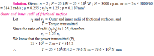
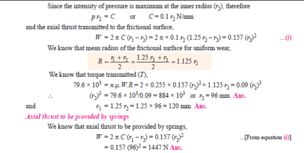
Simple band brake:
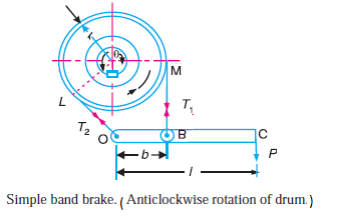
Given: Length of lever l = 40 cm = 0.4m, diameter d = 40 cm = 0.4, µ = 0.25, b =0 .08 m ϴ = Angle of wrap = 5/8 x 360 = 225 x π /180 = 3.93 rad Braking torque = (T1 –T2) x r T1/T2 = e µϴ = e 0.25 x 3.93 = 2.67 Taking moments about fulcrum P x l = b x T1 500 x 0.40 = 0.08 x T1 T1 = 2500 N T2 = 2500 / 2.67 = 936.3 N Braking Torque = (2500 – 936.3) x 0.2 = 312.74 N-m
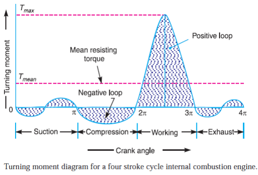
ii) Turning Moment Diagram:
i) Types of gear trains 1) Simple gear train 2) Compound gear train 2) Epicyclic gear train 4) Inverted gear train Simple gear train. When there is only one gear on each shaft, it is known as simple gear train. The gears are represented by their pitch circles. When the distance between the two shafts is small, the two gears are made to mesh with each other to transmit motion from one shaft to the other Epicyclic gear train: A simple epicyclic gear train is shown in Fig. where a gear A and the arm C have a common axis at O1about which they can rotate.
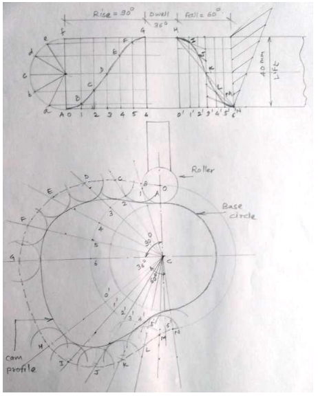
Fig shows a displacement diagram and a cam profile for the roller follower.
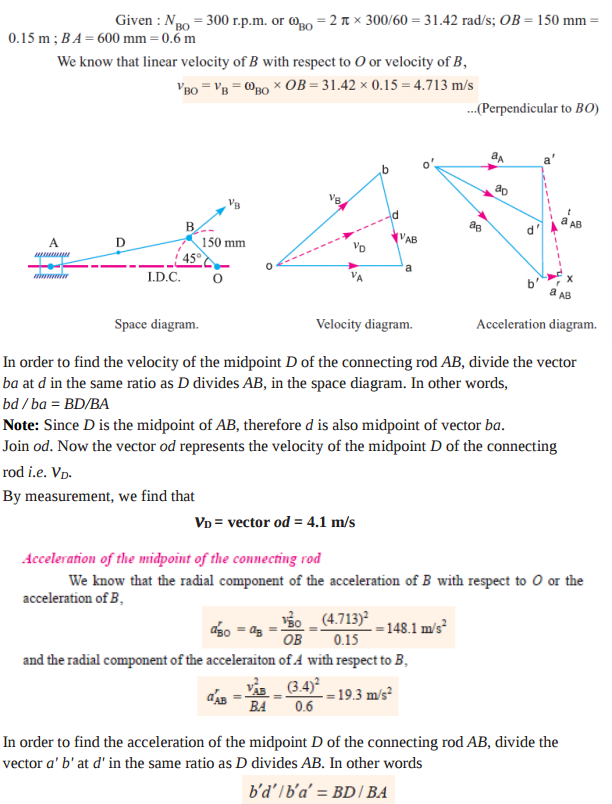
Note: Since D is the midpoint of AB, therefore d' is also midpoint of vector b' a'. Join o' d'. The vector o' d' represents the acceleration of midpoint D of the connecting rod i.e. aD.
By measurement, we find that aD = vector o' d' = 117 m/s2
Given: Lift = 40 mm Rise = ¼ x 360 = 900 Fall =1/6 x 360 = 600 Dwell = 1/10 x 360 =360
Given : m1 = 180 kg, m2 = 300 kg, m3 = 230 kg, m4 = 260 kg r1 = 0.2 m, r2 = 0.15 m, r3 = 0.25 m, r4 = 0.3 m ϴ1 = 45, ϴ2 = 75, ϴ = 135 The centrifugal forces are given by - m1r1 = 36, m2r2 = 45, m3r3 = 57.5, m4r4 = 78
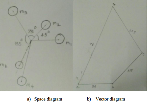
From vector diagram the resultant force is at 60 to the mass m1 and is represented by ar ar = 12 kg m Therefore mb * rb = 12 kgm Balancing mass mb = 12/0.2 = 60 kg at an angle of 2400 with the direction of m1 mass
Problem on Foot step bearing D = 225 mm = 0.225 m W = 7500 N µ = 0.09 N = 600 rpm ω = 2 π N / 60 =62.83 rad/sec Uniform pressure condition Frictional torque T = 2/3 µ W R = 50.625 Nm Power lost in friction = T x ω = 50.625 x 62.83 = 3180.8 W --------Ans Uniform wear condition Frictional torque T = 1/2 µ W R = 37.98 Nm Power lost in friction = T x ω = 37.98 x 62.83 = 2385.57 W -------- Ans