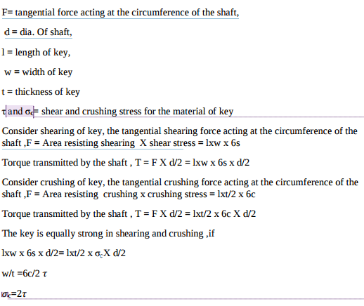
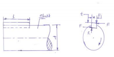
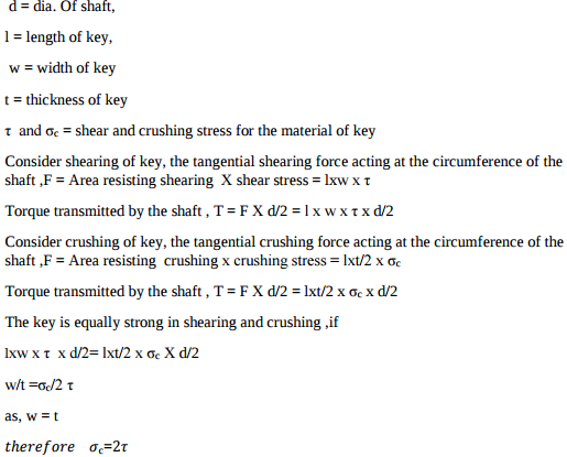
Prove that for a square key sc = 2t where sc = crushing stress t = shear stress.


bolts of uniform strength: if a shank dia.is reduced to a core dia.as shown in fig. the stress become same through out the length of the bolt. Hence impact energy is distributed uniformly throughout the bolt length, thus relieving the threaded portion of high stress. The bolt in this way becomes stronger and lighter. This type of bolt is known as bolt of uniform strength.Another method of obtaining the bolt of uniform strength is shown in fig.in this method, instead of reducing the shank dia.an axial hole is drilled through the head down to
Lewis equation: WT = σw.b.π.m.y, WT= Tangential load acting at the tooth in N σw= bending stress in N/mm2 b= width of the gear face in mm m= module in mm y= lewis form factor.

30 Ni 16 Cr5 : alloy steel carbon 0.3% of average, Nickel 16%, chromium 5% 40C8 : Plain carbon steel carbon 0.4% of average, manganese 0.8% FeE230 : Steel with yield strength of 230N/mm2
X15Cr25Ni12 : high alloy steel carbon 0.15% of average, chromium 25%, Nickel 12%,
Applications of cotter joint: cotter foundation bolt, big end of the connecting rod of a steam engine, joining piston rod with cross head, joining two rods with a pipe Applications of knuckle joint: link of bicycle chain, tie bar of roof truss, link of suspension bridge, valve mechanism, fulcrum of lever, joint for rail shifting mechanism
(i) Applications of maximum shear stress theory : for ductile material , crank shaft, propeller shafts , c frames (ii) Applications of maximum principle normal stress theory : for brittle material , machine spindle, machine beds , c frames, overhang crank

T= Torque transmitted by the shaft , F= tangential force acting at the circumference of the shaft,

In the first type of levers, the fulcrum is in between the load and effort. In this case, the effort arm is greater than load arm, therefore M.A. obtained is more than 1 Application: Bell crank levers used in railway signaling arrangement, rocker arm in I.C. Engines , handle of a hand pump, hand wheel of a punching press, beam of a balance, foot lever (any 1) In the second type of levers, the load is in between the fulcrum and effort. In this case, the effort arm is more than the load arm, therefore M.A. is more than 1.
Given : P= 50 KW = 50000W Speed = 600rpm k=Di/do = 0.8 σyt= 380 N/mm2 Factor of safety= 4 Design stress σt=σyt/fos =380/4 =95 Shear stress = τ =σt/2 = 95/2 =47.5N/mm2 Torque transmitted by hollow shaft T = P x 60/2πN T = 50000 x 60/2π x600 T = 795.67 N-m T= 795670 Nmm T= π/16 Xτ X do3 (1-k 4 ) 795670 =π/16 X 47.5 X do3 ( 1-0.84 ) Do3=144529.313 Do = 53 mm say 55 mm Di = 0.8X 55 = 44mm