CPS Question and answers
| Que.No | Question/Problem | marks | Link |
|---|---|---|---|
| Q ) |
Question:
State one application of each : v-belt drive, flat belt drive, chain drive and gear drive. Answer:
|
4 |
view |
| Q 3 a ) |
Question:
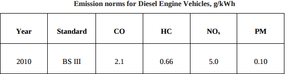
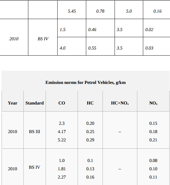
State the norms of Bharat stage III and IV. Answer:
|
4 |
view |
| Q 4a)(iii) |
Question:
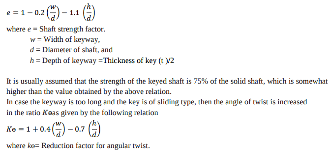
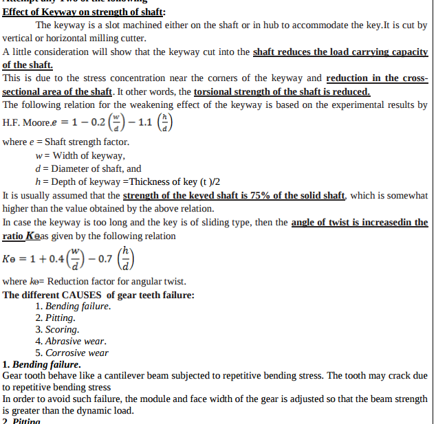
State the effect of keyway on the strength of the shaft. Answer:
|
4 |
view |
| Q 5 c ) |
Question:
Draw psychrometric chart with all the property lines and represent following psychrometric Answer:
|
8 |
view |
| Q 6 b ) |
Question:
Define : i) Free air delivered ii) Compressor capacity iii) Swept volume iv) Pressure ratio, w.r.to compressor. Answer:
|
4 |
view |
| Que.No | Question/Problem | marks | Link |
|---|---|---|---|
| Q 1 a ) |
Question:
Define inversion with example. Answer:
|
2 |
view |
| Q 1a)(a) |
Question:
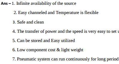
Enlist uses of compressed air (any four). Answer:
|
4 |
view |
| Q 1a)(a) |
Question:
What is function of (i) oil reservoir (ii) pressure relief valve, (iii) direction control valve, (iv) filters ? Answer:
|
4 |
view |
| Q 1a)(b) |
Question:
What are the advantages of multistaging ? Answer:
|
4 |
view |
| Q 1a)(b) |
Question:
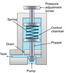
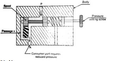
Draw and explain working of pressure reducing valve. Answer:
|
4 |
view |
| Q 1a)(c) |
Question:
Classify gas turbines (any four) Answer:
 |
4 |
view |
| Q 1a)(c) |
Question:
Explain piston pump with neat sketch. Answer:
|
4 |
view |
| Q 1a)(d) |
Question:
Define : Answer:
|
4 |
view |
| Q 1a)(d) |
Question:
What is an accumulator ? Why accumulator is necessary for huge hydraulic pressers ? Answer:
|
4 |
view |
| Q 1a)(ii) |
Question:
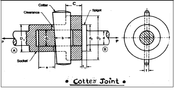
What is a cotter joint? State any four applications of a cotter joint? Why taper is provided on cotter joint? Answer:
|
8 |
view |
| Q 1a)(iii) |
Question:
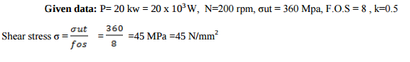
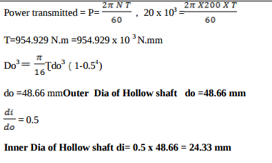
A hollow shaft for a rotary compressor is to be designed to transmit maximum torque of 4750 N-m. The shear stress in the shaft is limited to 50 MPa. Determine the inside outside diameter of the shaft if the ratio of inside to outside diameter of the shaft is 0.4. Answer:
|
8 |
view |
| Q 1 b ) |
Question:
List the inversions for double slider crank mechanism. Answer:
|
2 |
view |
| Q 1b)(a) |
Question:
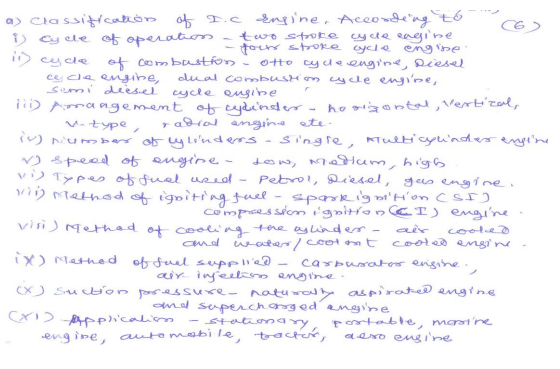
Give classification of IC engines (any six). Answer:
 |
6 |
view |
| Q 1b)(a) |
Question:
Write the causes and remedies for the following : (i) Excess heat in oil (ii) Noisy pump (iii) Low pressure in system. Answer:
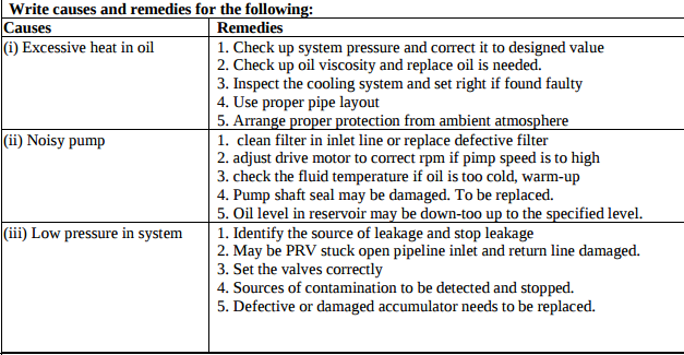 |
6 |
view |
| Q 1b)(b) |
Question:
What is pressure compensated flow control valve ? Explain with sketch. Answer:
|
6 |
view |
| Q 1b)(b) |
Question:
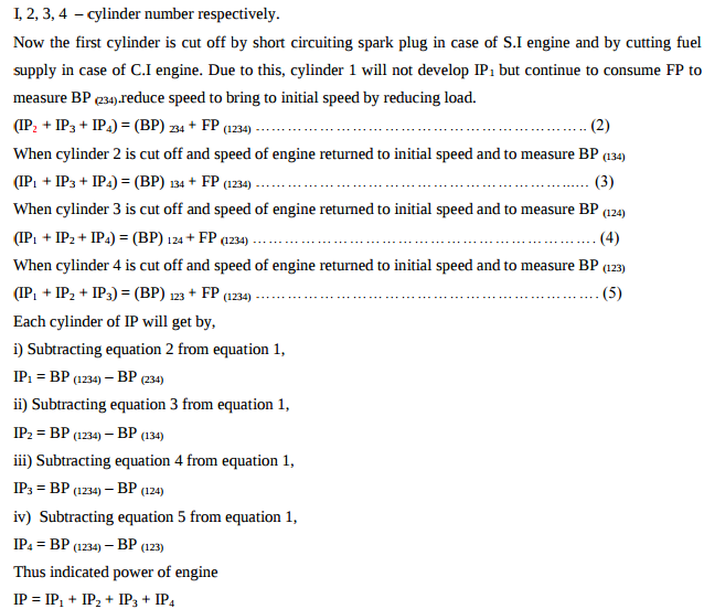
Explain Morse test conducted to find the frictional power of a multi-cylinder petrol engine Answer:
|
6 |
view |
| Q 1b)(i) |
Question:
i) What are the factors to be considered for selection of materials for design of machine elements? Answer:
|
6 |
view |
| Q 1b)(ii) |
Question:
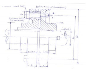
Design a bushed pin type flexible coupling for connecting a motor shaft to a pump shaft for the following service conditions. Power to be transmitted = 40 KW. Speed of the motor shaft = 1000 RPM. Diameter of the motor shaft = 50 mm Diameter of the pump shaft = 45 mm The bearing pressure in the rubber bush and allowable stress in the pins are to be limited to 0.45 N/mm2 and 25 MPa respectively Answer:
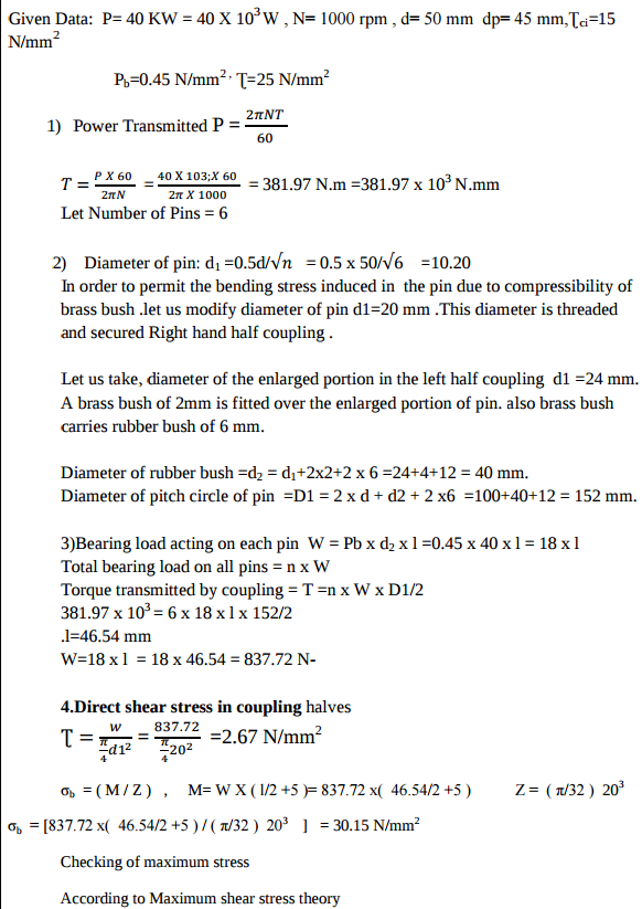  |
6 |
view |
| Q 1 c ) |
Question:
Define sliding pair with example. Answer:
|
2 |
view |
| Q 1 d ) |
Question:
Define centripetal and tangential acceleration. Answer:
|
2 |
view |
| Q 1 e ) |
Question:
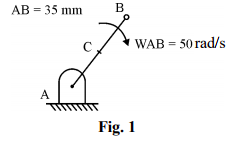
Find the velocity of point B and midpoint C of link AB shown in Figure (1). Answer:
|
2 |
view |
| Q 1 f ) |
Question:
Classify the cam. Answer:
|
2 |
view |
| Q 1 g ) |
Question:
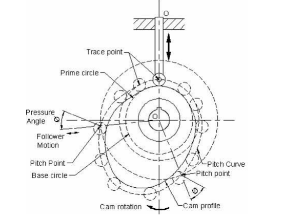
Define following terms with respect to cam and follower : (i) Prime circle (ii) Pitch circle (iii) Pressure angle (iv) Trace point
Answer:
|
2 |
view |
| Q 1 h ) |
Question:
What are the limitations of knife edge follower ? Answer:
|
2 |
view |
| Q 1 i ) |
Question:
Define self-energizing and self-locking brake. Answer:
|
2 |
view |
| Q 1 i ) |
Question:
Write down the formula of length of belt for open belt drive and cross belt drive. Answer:
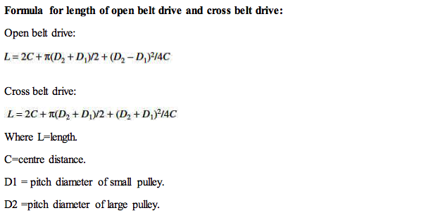 |
2 |
view |
| Q 1 i ) |
Question:
List the methods to reduce the slip in belt and pulley. Answer:
|
2 |
view |
| Q 1 k ) |
Question:
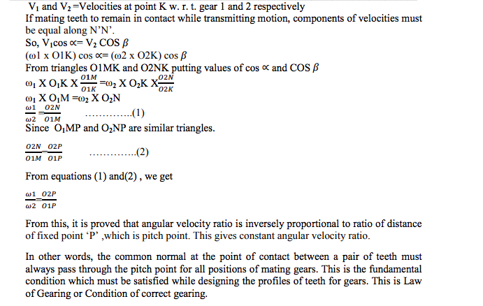
Define law of gearing. Answer:
|
2 |
view |
| Q 1 l ) |
Question:
What is factor of safety? State its importance in design of machine elements. Answer:
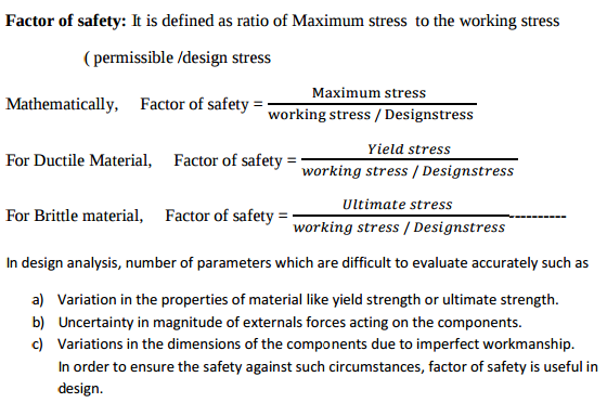 |
8 |
view |
| Q 1 m ) |
Question:
What are the limitations of shoe brake ? Answer:
|
2 |
view |
| Q 1 n ) |
Question:
Define uniform wear theory and uniform pressure theory. Answer:
|
2 |
view |
| Q 1 o ) |
Question:
State effects of imbalance in machine. Answer:
|
2 |
view |
| Q 2 a ) |
Question:
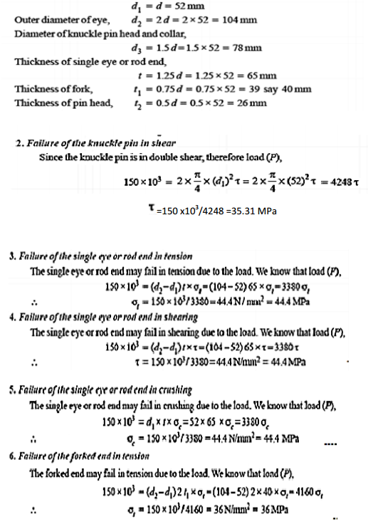
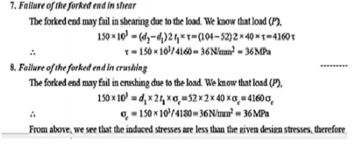
Design a knuckle joint to transmit 150 KN. The design stresses may be taken as 75 MPa in tension, 60 MPa in shear and 150 MPa in compression. Answer:
|
8 |
view |
| Q 2 a ) |
Question:
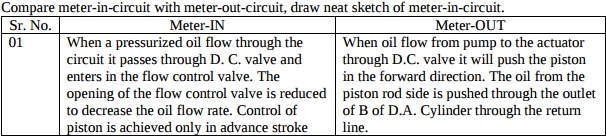
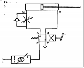
Compare meter-in-circuit with meter-out-circuit, draw neat sketch of meter-in-circuit. Answer:
  |
8 |
view |
| Q 2 a ) |
Question:
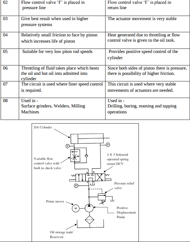
Draw a neat sketch and explain working of beam engine. Answer:
 |
4 |
view |
| Q 2 a ) |
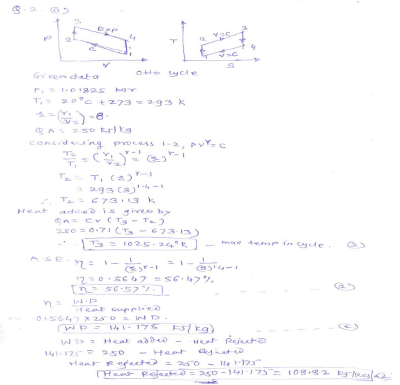
Question:
In an Ideal ottocycle the air at the beginning of isentropic compression is at 1.01325 bar and Answer:
 |
8 |
view |
| Q 2 b ) |
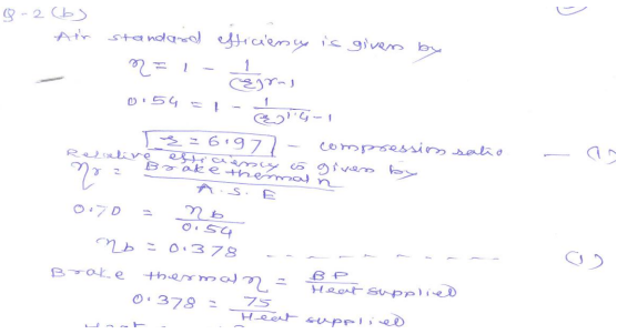
Question:
The following data refers to a trial conducted on 4-stroke petrol engine Answer:
  |
8 |
view |
| Q 2 b ) |
Question:
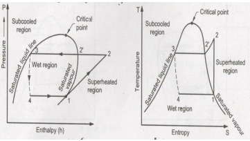
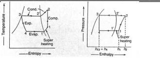
Explain vapour compression refrigeration cycle on T-S and p-h charts (for superheated vapourat the end of compression) Answer:
|
8 |
view |
| Q 2 b ) |
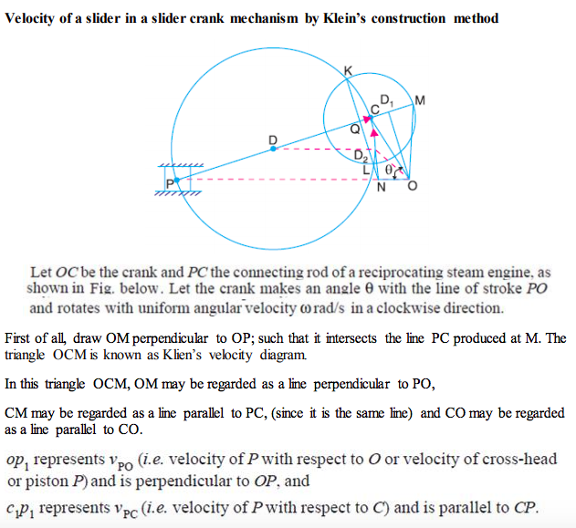
Question:
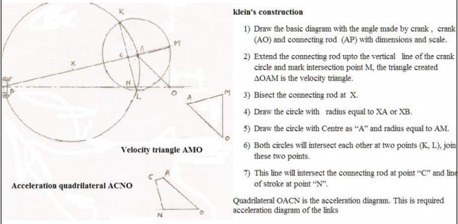
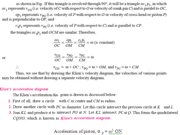
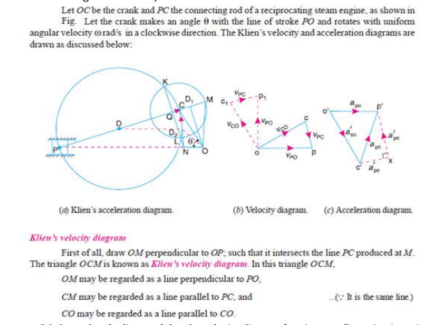
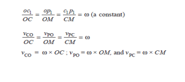
Explain with neat sketch how to find the velocity of a slider in slider crank mechanism by Klein’s construction. Answer:
 |
2 |
view |
| Q 2b)(ii) |
Question:
Draw neat sketch of a protected type flanged coupling showing all details. Answer:
|
8 |
view |
| Q 2b)(l) |
Question:
(i) State and explain two most important reasons for adopting involute curves for a gear tooth profile Answer:
|
8 |
view |
| Q 2 c ) |
Question:
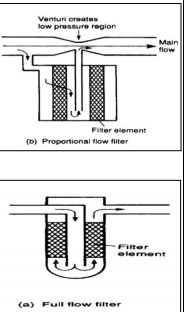
What is function of filters ? Classify the filters and draw any two types of filters Answer:
|
8 |
view |
| Q 2 c ) |
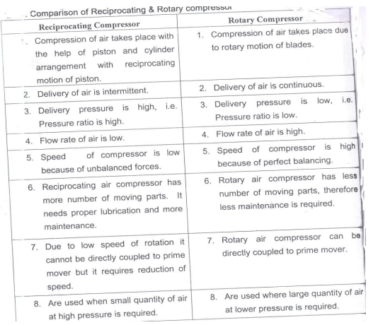
Question:
Differentiate between reciprocating air compressor and rotary air compressor......... Answer:
 |
8 |
view |
| Q 2 c ) |
Question:
Draw and explain in short, types of followers used in cam and follower. Answer:
|
4 |
view |
| Q 2c)(i) |
Question:
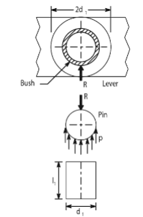
Why are bushes of softer material inserted in the eyes of levers? Answer:
 |
8 |
view |
| Q 2c)(ii) |
Question:
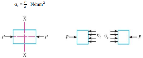
Explain the following types of stresses Answer:
  |
8 |
view |
| Q 2 d ) |
Question:
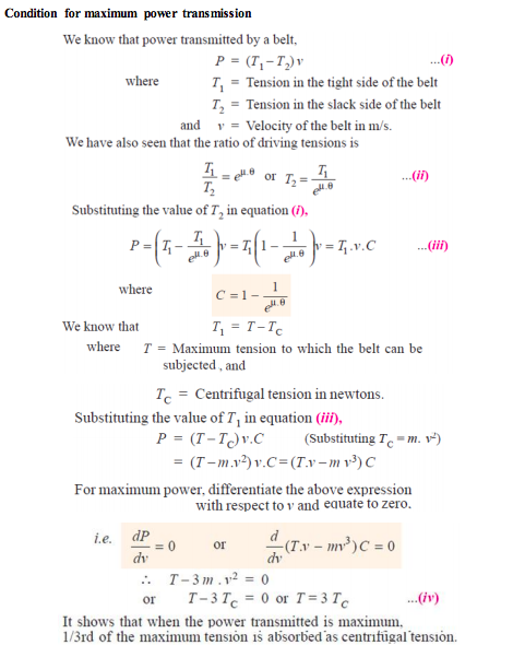
Explain condition for maximum power transmission. Answer:
 |
4 |
view |
| Q 2 e ) |
Question:
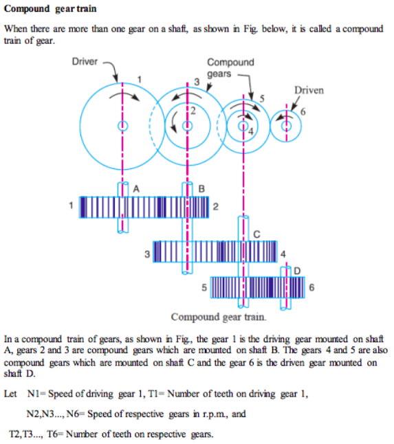
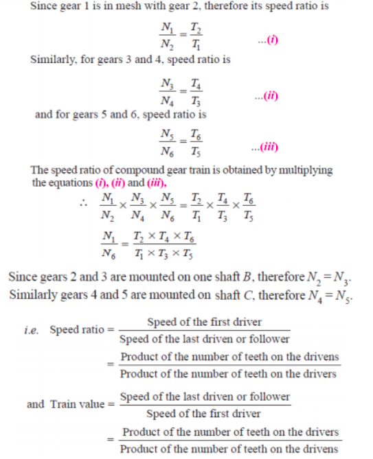
Explain the compound gear train with neat sketch and write down the velocity ratio’s equation. Answer:
  |
4 |
view |
| Q 2 f ) |
Question:
A multiplate clutch has three pairs of contact surfaces. The outer and inner radii of the contact surfaces are 100 mm and 50 mm respectively. The maximum axial spring force is limited to 1.25 kN. If the co-efficient of friction is 0.35 and assuming uniform wear, find the power transmitted by the clutch at 1600 rpm. Answer: |
4 |
view |
| Q 3 ) |
Question:
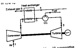
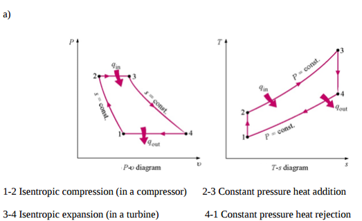
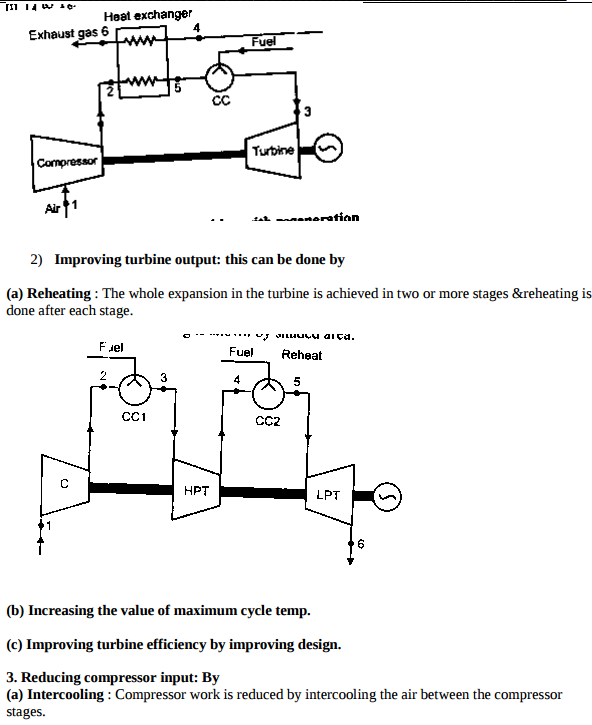
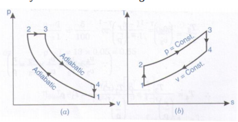
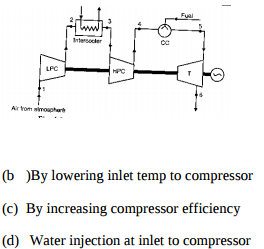
Represent Brayton cycle on PV and TS diagram. Name the processes completing the cycle Answer:
 |
4 |
view |
| Q 3 a ) |
Question:
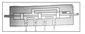
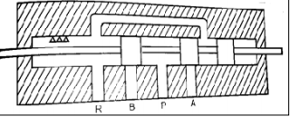
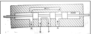
Explain 4-way-3 position direction control valve used in hydraulic system. Answer:
|
4 |
view |
| Q 3 a ) |
Question:
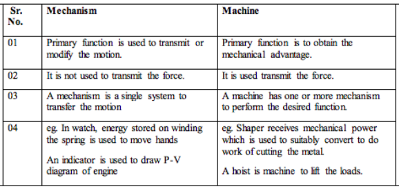
Differentiate between mechanism and machine. Answer:
 |
4 |
view |
| Q 3 b ) |
Question:
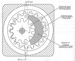
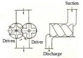
Explain gear pump with neat sketch. Answer:
|
4 |
view |
| Q 3 b ) |
Question:
A petrol engine has a cylinder of diameter 60 mm and stroke 100 mm. If the mass of charge Answer:
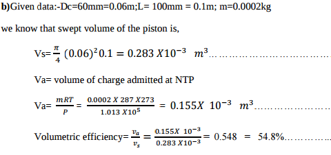 |
4 |
view |
| Q 3 b ) |
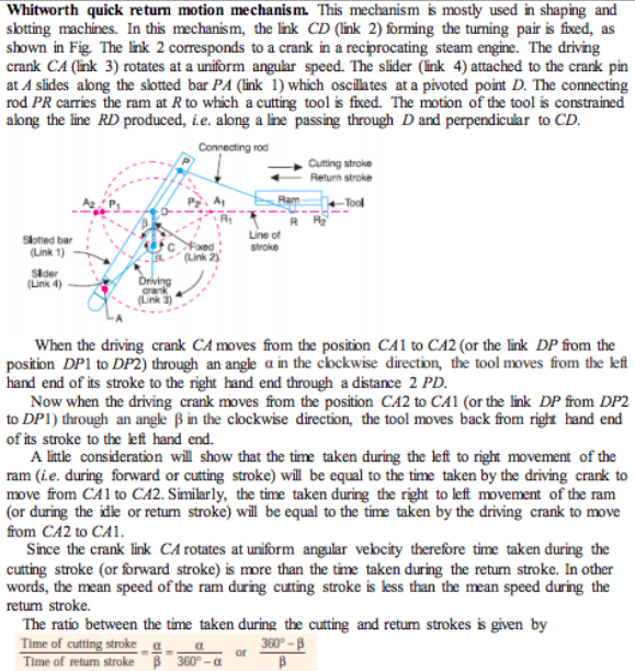
Question:
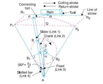
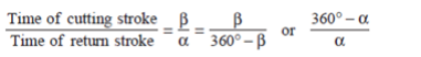
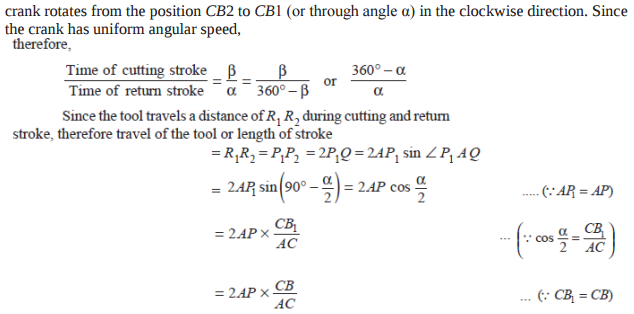
Explain the working of Whitworth quick return mechanism. Answer:
 |
4 |
view |
| Q 3 b ) |
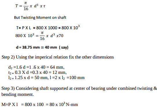
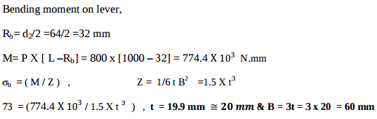
Question:
Design a foot brake lever from the following data: Length of lever from C.G. of the spindle to the point of application of the load = 1 meter. Max. load on the foot plate = 800 N Overhang from the nearest bearing = 100 mm Permissible tensile and shear stress = 70 MPa. Answer:
|
4 |
view |
| Q 3 c ) |
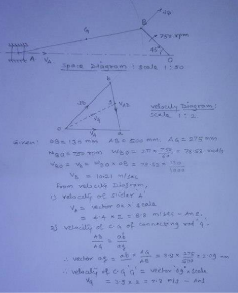
Question:
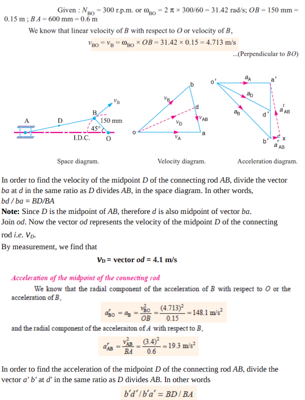
In slider crank mechanism, the length of crank OB and connecting rod AB are 130 mm and 500 mm respectively. The centre of gravity G of the connecting rod is 275 mm from slider A. The crank speed is 750 rpm in clockwise. When crank has turned 45 from inner dead centre position determine (i) velocity of slider ‘A’ (ii) velocity of centre of gravity of connecting rod ‘G’. Answer:
 |
4 |
view |
| Q 3 c ) |
Question:
Explain any four criteria for selection of hydraulic pump in hydraulic system. Answer:
|
4 |
view |
| Q 3 c ) |
Question:
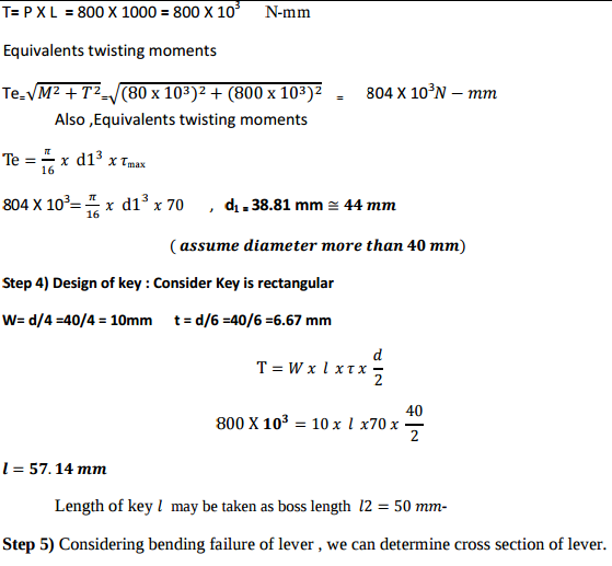
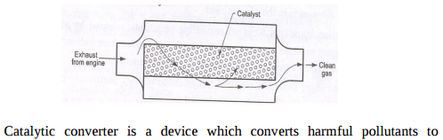
Explain with neat sketch two way catalytic converter. Answer:
|
4 |
view |
| Q 3 d ) |
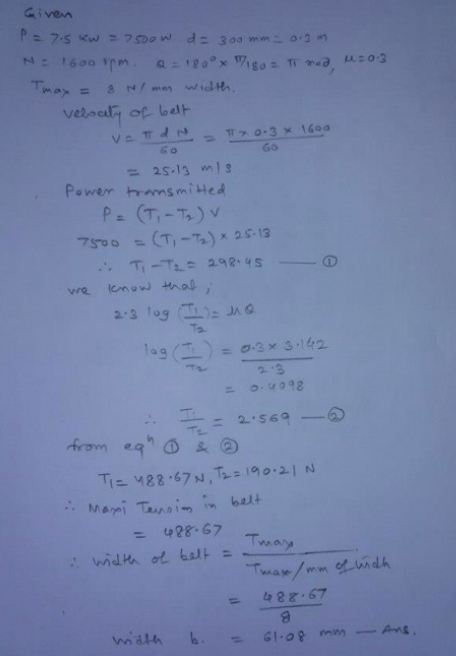
Question:
Find the width of the belt, necessary to transmit 7.5 kW to a pulley 300 mm diameter, if the pulley makes 1600 rpm and the co-efficient of friction between the belt and pulley is 0.3. Assume the angle of contact as 180o and the maximum tension in the belt is not to exceed 8 N/mm width. Answer:
 |
4 |
view |
| Q 3 d ) |
Question:
Name any four components of pneumatic system. What are the factors considered while selecting them ? Answer:
|
4 |
view |
| Q 3 d ) |
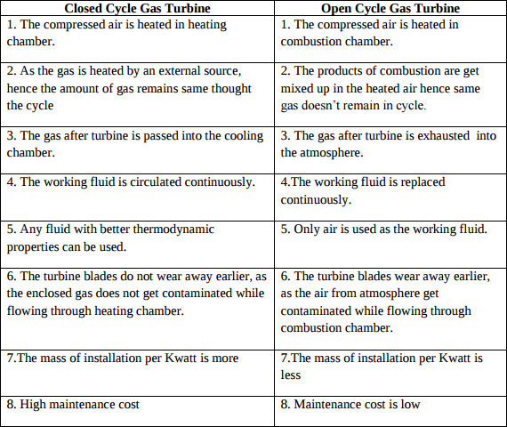
Question:
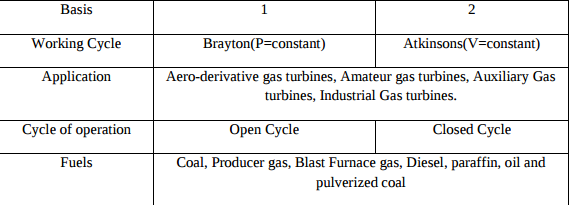
Differentiate between closed cycle and open cycle gas turbine Answer:
 |
4 |
view |
| Q 3 d ) |
Question:
Compare welded joints with screwed joints. (Any six points) Answer:
|
4 |
view |
| Q 3 e ) |
Question:
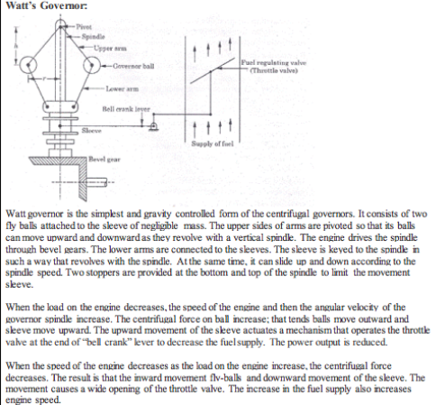
Explain the working of Watt governor with neat diagram. Answer:
 |
4 |
view |
| Q 3 e ) |
Question:
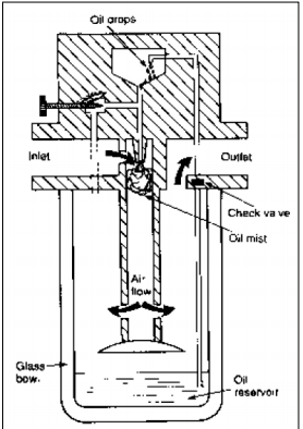
Draw labelled sketch of air lubricator. Answer:
 |
4 |
view |
| Q 3 e ) |
Question:
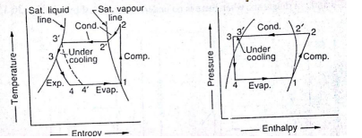
Explain the effect of superheating and subcooling on the performance of vapour compression cycle Answer:
|
4 |
view |
| Q 3 e ) |
Question:
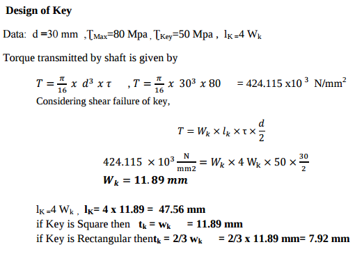
A shaft 30 mm. diameter is transmitting power at a maximum shear stress of 80 MPa. If a pulley is connected to the shaft by means of a key, find the dimension of the key so that stress in the key is not to exceed 50 MPa and length of the key is 4 times the width. Answer:
 |
4 |
view |
| Q 3 f ) |
Question:
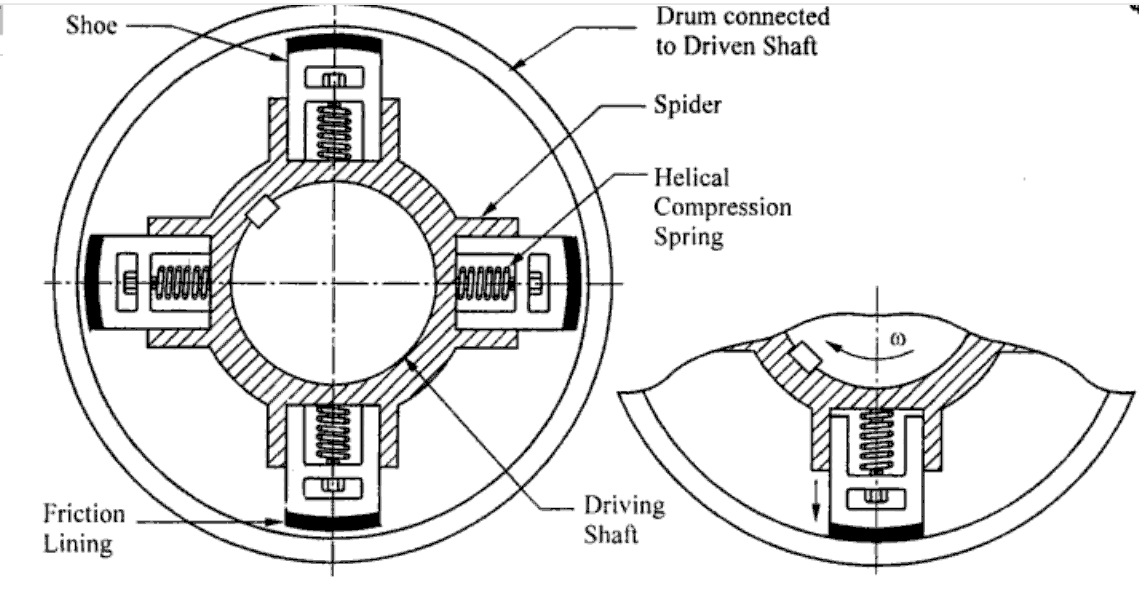
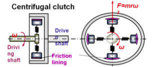
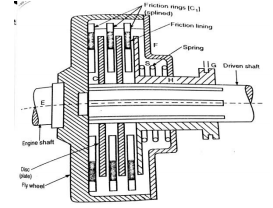
Explain the working of centrifugal clutch with neat sketch. Answer:
|
4 |
view |
| Q 4 a ) |
Question:
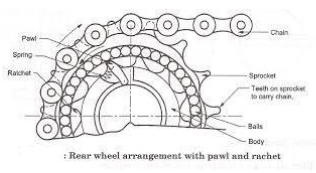
Explain the working of freewheel mechanism of bicycle with sketch. Answer:
|
4 |
view |
| Q 4a)(a) |
Question:
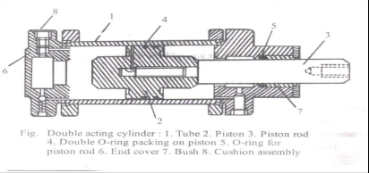
What are actuators ? Draw a double acting cylinder. Answer:
|
4 |
view |
| Q 4a)(a) |
Question:
a) Define : Answer:
|
6 |
view |
| Q 4a)(b) |
Question:
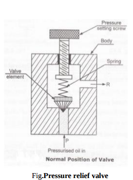
Explain pressure relief valve in pneumatic system. Answer:
 |
4 |
view |
| Q 4a)(b) |
Question:
Explain with sketch working of screw compressor. Answer:
|
4 |
view |
| Q 4a)(c) |
Question:
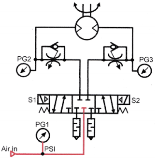
Explain with sketch, a pneumatic circuit for speed control of bidirectional motor. Answer:
|
4 |
view |
| Q 4a)(c) |
Question:
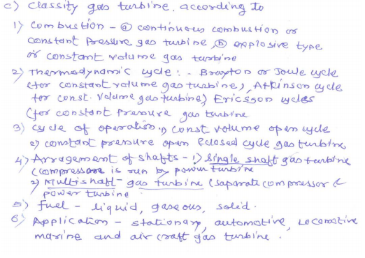
Classify gas turbines on the following basis : i) Working cycle ii) Application iii) Cycle of operation iv) Fuels Answer:
 |
4 |
view |
| Q 4a)(d) |
Question:
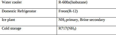
Name the refrigerants used for : i) Water cooler ii) Domestic refrigerator iii) Ice plant iv) Cold storage. Answer:
 |
4 |
view |
| Q 4a)(d) |
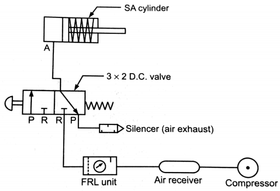
Question:
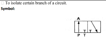
State any two applications of 3 × 2 DC valve. Draw symbol for the same. Answer:
|
4 |
view |
| Q 4a)(i) |
Question:
a) Attempt any THREE of the following: 12 (i) Give the composition of : 1) 35Mn 2 Mo28 2) 30Ni 4 Crl and 3) 25 Cr 3 Mo 55 Answer:
|
4 |
view |
| Q 4a)(ii) |
Question:
Define following terms with respect to springs : 1) Free length 2) Solid height 3) Spring rate 4) Spring index Answer:
|
4 |
view |
| Q 4a)(iii) |
Question:
Explain effect of keyways on strength of shaft. Name one type of key which does not affect strength of shaft Answer:
|
4 |
view |
| Q 4a)(iv) |
Question:
Define following terms w.r.t. bolts: 1) Major diameter 2) Minor diameter 3) Pitch 4) Lead Answer:
|
4 |
view |
| Q 4 b ) |
Question:
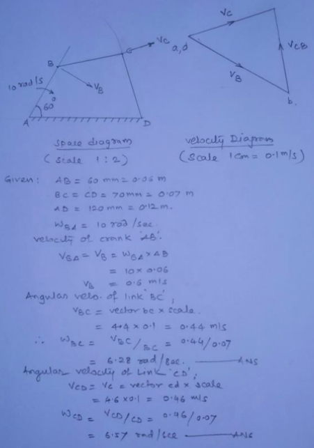
In a four bar mechanism ABCD link AD is fixed and the crank AB rotates at 10 radians per second in clockwise, lengths of the links are AB = 60 mm, BC = CD = 70 mm, DA = 120 mm, when angle DAB = 60 and both B and C lie on the same side of AB, find angular velocities of BC and CD link. Answer:
 |
4 |
view |
| Q 4b)(a) |
Question:
Explain with neat sketch the working of variable displacement vane pump. Answer:
|
6 |
view |
| Q 4b)(b) |
Question:
Compare pressure relief valve and pressure reducing valve. Answer: |
6 |
view |
| Q 4b)(i) |
Question:
(i) Explain different causes of gear tooth failure and suggest possible remedies to avoid such failures Answer:
|
6 |
view |
| Q 4b)(ii) |
Question:
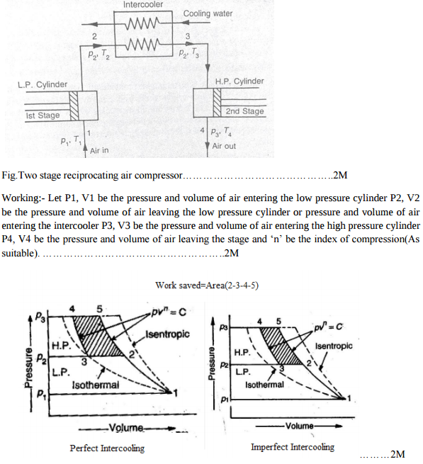
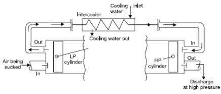
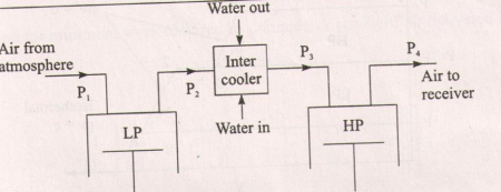
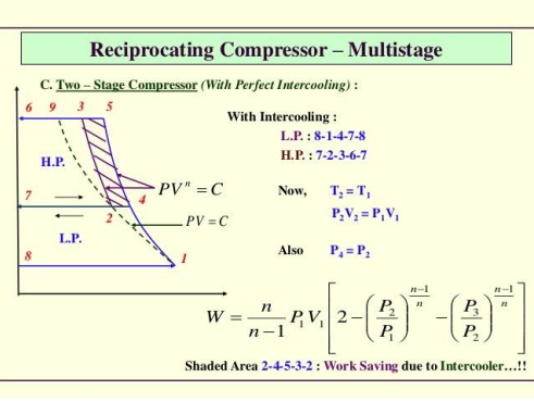
Explain the working of two stage reciprocating compressor. Show work saved on PV diagram. Answer:
 |
6 |
view |
| Q 4b)(ii) |
Question:
Explain the importance of Aesthetic considerations in design by giving any two examples. Answer:
|
6 |
view |
| Q 4b)(l) |
Question:
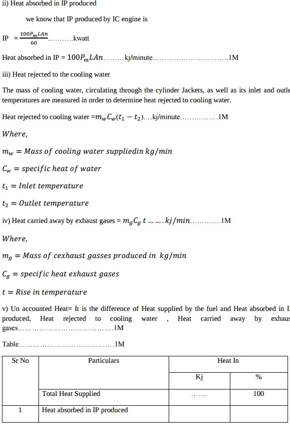
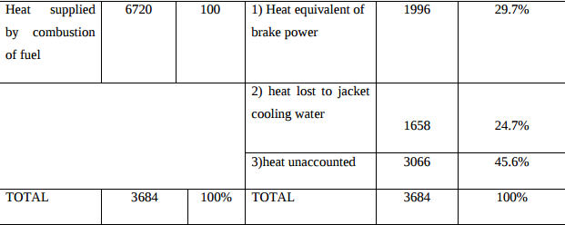
Explain how the heat balance sheet for an IC engine is prepared ? Answer:
|
6 |
view |
| Q 4 c ) |
Question:
What are the advantages of ‘V’ belt drive over flat belt drive ? Answer:
|
4 |
view |
| Q 4 d ) |
Question:
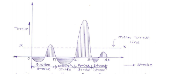
Explain the working of flywheel with the help of turning moment diagram. Answer:
|
4 |
view |
| Q 4 e ) |
Question:
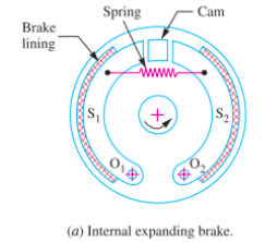
Explain the working of internal expanding brake with neat sketch. Answer:
|
4 |
view |
| Q 4 f ) |
Question:
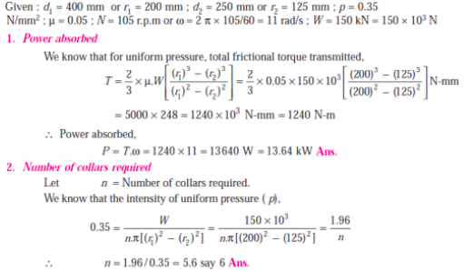
A shaft has number of collars integral with it. The external diameter of the collars is 400 mm and the shaft diameter is 250 mm. If the uniform intensity of pressure is 0.35 N/mm2 and its co-efficient of friction is 0.05; find (i) power absorbed in overcoming friction when shaft rotates at 105 rpm and carries a load of 150 kN, and (ii) number of collars required. Answer:
 |
4 |
view |
| Q 5 a ) |
Question:
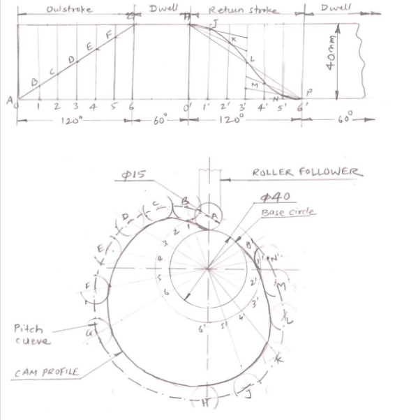
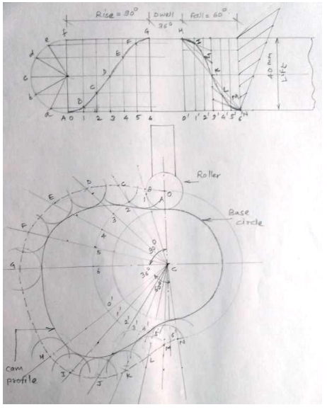
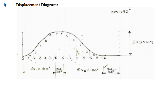
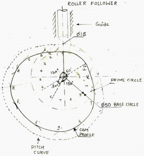
A cam with 40 mm minimum diameter rotates in clockwise at uniform speed and has to give the following motion to a roller follower 15 mm diameter : (i) Follower to complete outward stroke of 40 mm during 120o of cam rotation with uniform velocity. (ii) Follower to dwell for 60o of cam rotation. (iii) Follower will return to its initial position during 120 of cam rotation with uniform acceleration and retardation. (iv) Follower will dwell for remaining 60o of cam rotation. Draw the profile of cam, if the axis of follower passes through the axis of cam. Answer:
 |
8 |
view |
| Q 5 a ) |
Question:
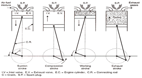
Explain the working of four stroke petrol engine with neat sketch. OR Explain with diagram how the Four stroke petrol engine works. Answer:
|
8 |
view |
| Q 5 a ) |
Question:
List the factors to be considered for selecting the pipe while designing the pneumatic system. Give specification of pipes for the pneumatic system. Answer:
|
8 |
view |
| Q 5a)(i) |
Question:
(i) Show that the efficiency of a self locking screw is less than 50% Answer:
|
8 |
view |
| Q 5a)(ii) |
Question:
What is self locking property of threads and where it is necessary? Answer:
|
8 |
view |
| Q 5 b ) |
Question:
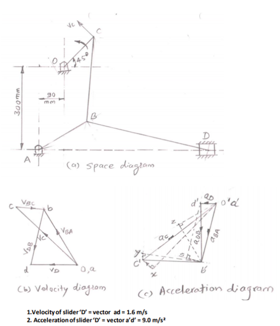
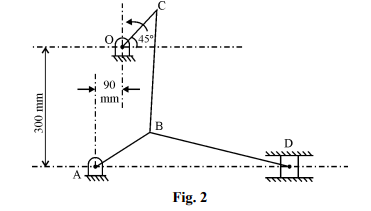
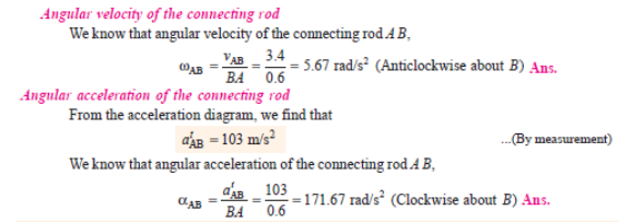
In the toggle mechanism as shown in Fig. (2), D is constrained to move on a horizontal path. The dimensions of various links are AB = 200 mm, BC = 300 mm, OC = 150 mm and BD = 450 mm. The crank OC is rotating in a counter clockwise direction at a speed of 180 rpm. Find, for given configuration (1) velocity and (2) acceleration of ‘D’.
Answer:
 |
8 |
view |
| Q 5 b ) |
Question:
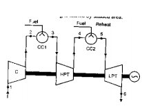
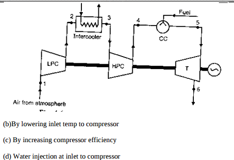
State the methods used to improve thermal efficiency of gas turbine and explain any one. Answer:
|
8 |
view |
| Q 5 b ) |
Question:
Draw and explain pneumatic meter in circuit to control of speed extension. Answer:
|
8 |
view |
| Q 5b)(i) |
Question:
(i) The extension springs are in considerably less use than compression springs. Why? Answer:
|
8 |
view |
| Q 5b)(ii) |
Question:
Explain the terms self locking and overhauling of screw. Answer:
|
8 |
view |
| Q 5 c ) |
Question:
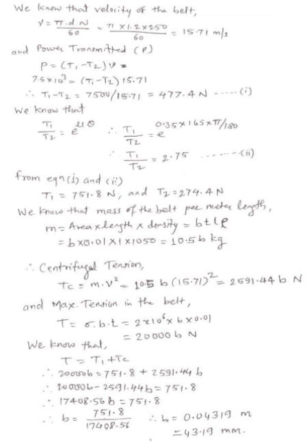
A leather belt is required to transmit 7.5 kW from a pulley 1.2 m in diameter running at 250 rpm. The angle of contact is 165o and the co-efficient of friction between the belt and the pulley is 0.35. If the safe working stress for the leather belt is 2 MPa, density of leather is 1050 kg/m3 and the thickness of belt is 10 mm, determine the width of belt, taking centrifugal tension into account. Answer:
 |
8 |
view |
| Q 5 c ) |
Question:
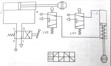
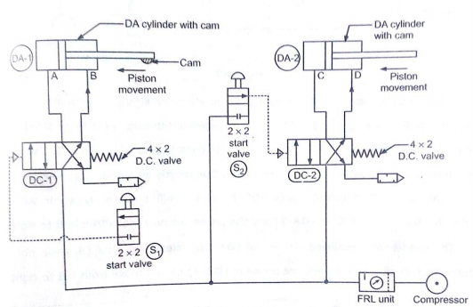
Explain with neat sketch (position based) working of sequencing circuit for two double acting Air cylinders. Answer:
|
8 |
view |
| Q 5c)(i) |
Question:
Define following terms as applied to rolling contact bearings: 1) Basic static load rating 2) Basic dynamic load rating 3) Limiting speed Answer:
|
8 |
view |
| Q 5c)(ii) |
Question:
List important physical characteristics of good bearing material. Answer:
|
8 |
view |
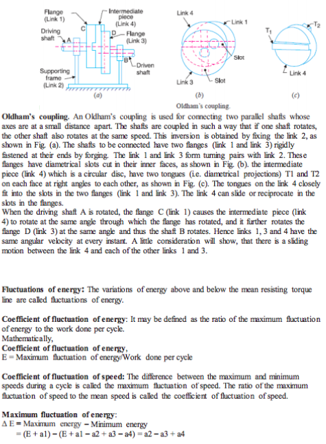
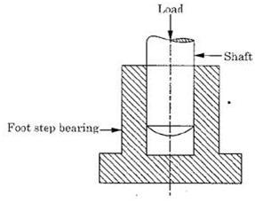
| Q 6 a ) |
Question:
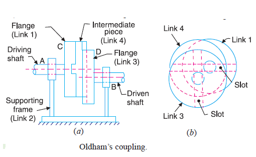
Draw a neat sketch of Oldham’s coupling and explain the working of it. Answer:
 |
4 |
view |
| Q 6 a ) |
Question:
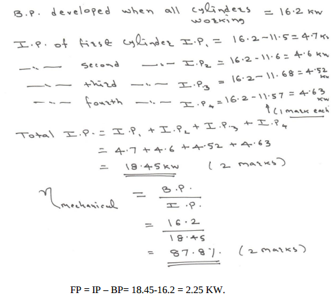
The following results were obtained during Morse test on 4 stroke petrol engine Answer:
|
4 |
view |
| Q 6 a ) |
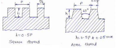
Question:
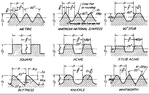
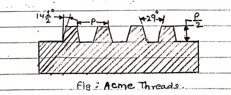
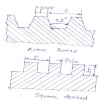
Draw profiles to square and Acme threads with full details. Which one is stronger? Answer:
|
4 |
view |
| Q 6 a ) |
Question:
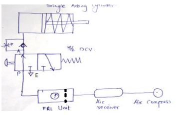
Draw speed control of single acting cylinder pneumatic circuit using 3 × 2 DC valve Answer:
 |
4 |
view |
| Q 6 b ) |
Question:
Define following terms : Fluctuation of energy, co-efficient of fluctuation of energy, co-efficient of fluctuation speed, maximum fluctuation of energy. Answer:
|
4 |
view |
| Q 6 b ) |
Question:
What is the necessity of purification of air ? How to remove oil, moisture and dust from air? Answer:
|
4 |
view |
| Q 6 b ) |
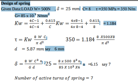
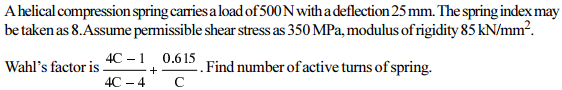
Question:
A helical valve spring is to be designed for an operating load range of approximately 135 N. The deflection of the spring for the load range is 7.5 mm. Assume spring index of 10. Permissible shear stress for the material of the spring = 480 MPa and its modulus of rigidity = 80 KN/mm2. Design the spring. Take Wahle’s factor 4 4 4 1 . , C C C 0 615 = - - + ‘C’ being the spring index Answer:
|
4 |
view |
| Q 6 b ) |
Question:
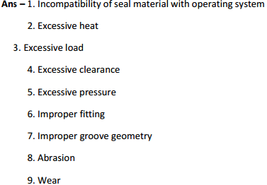
State any four reasons of failure of pneumatic seals. Answer:
|
4 |
view |
| Q 6 b ) |
Question:
State any four reasons of failure of pneumatic seals. Answer:
 |
4 |
view |
| Q 6 c ) |
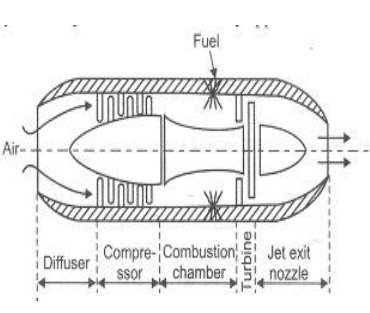
Question:
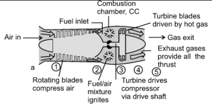
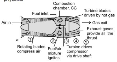
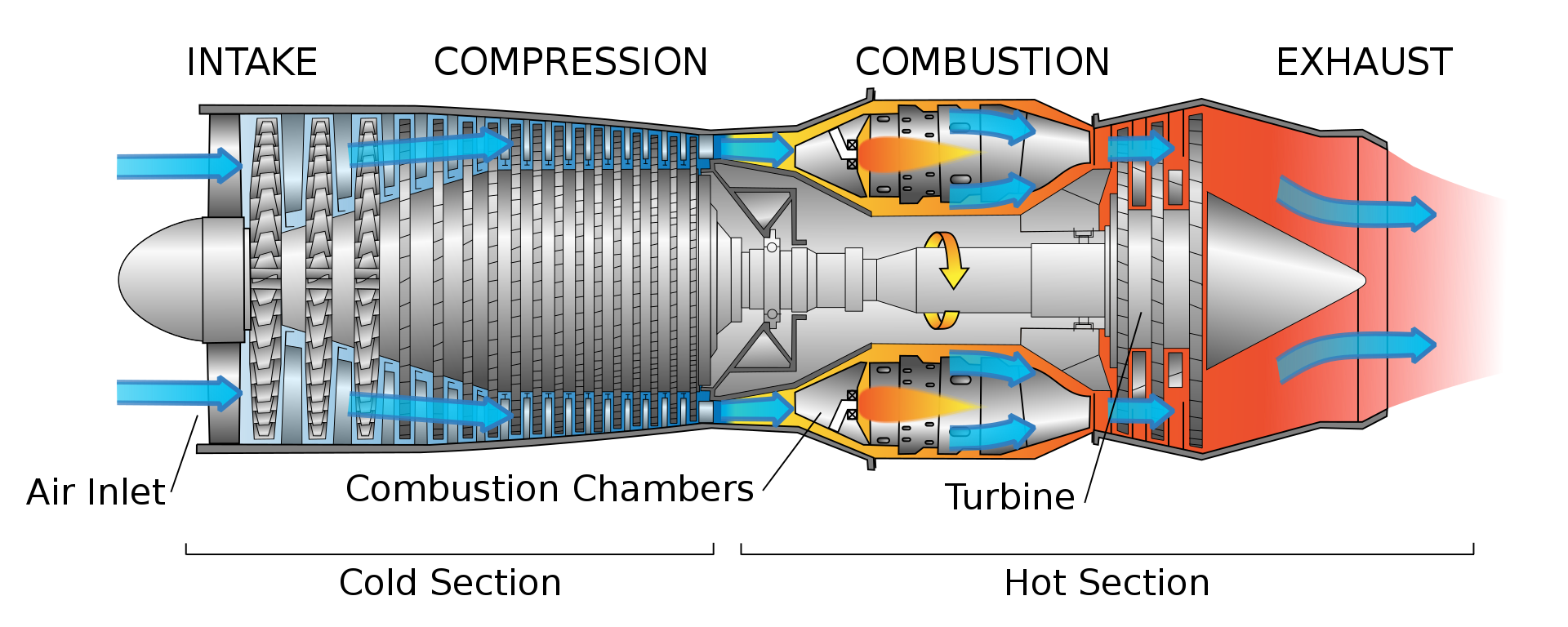
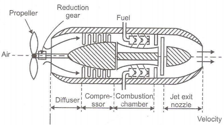
Draw the schematic diagram of turbojet engine. Answer:
|
4 |
view |
| Q 6 c ) |
Question:
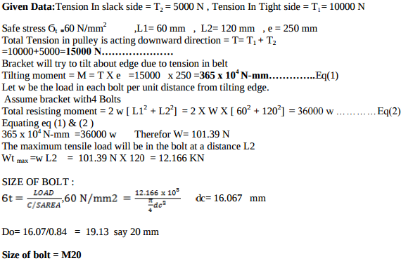
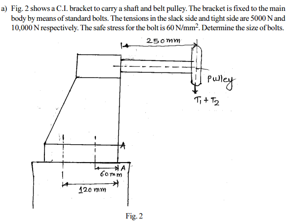
A bracket as shown in Figure No. 1 is fixed to a vertical steel column by means of five standard bolts.
Answer:
|
4 |
view |
| Q 6 c ) |
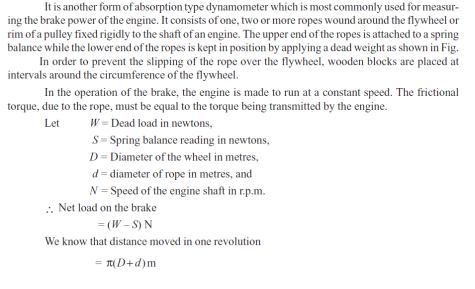
Question:
Explain the working of rope brake dynamometer with neat sketch Answer:
  |
4 |
view |
| Q 6 c ) |
Question:
(c) What are the advantages of pneumatic system over hydraulic systems ? Answer:
 |
4 |
view |
| Q 6 d ) |
Question:
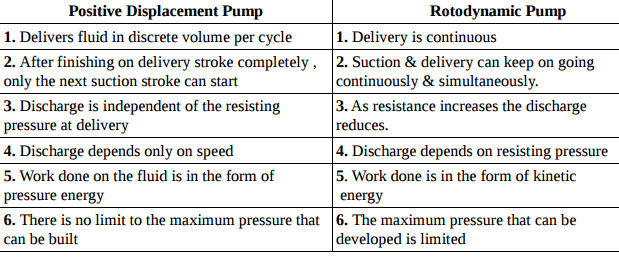
Compare positive displacement pump with Rotodynamic pump. Answer:
 |
4 |
view |
| Q 6 d ) |
Question:
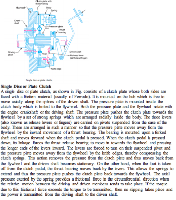
Explain the working of single plate clutch with neat diagram. Answer:
 |
4 |
view |
| Q 6 d ) |
Question:
What are rolling contact bearings? State their advantages over sliding contact bearings. Answer:
|
4 |
view |
| Q 6 d ) |
Question:
Define : i) WBT ii) DPT iii) DBT iv) Degree of saturation. Answer:
|
4 |
view |
| Q 6 e ) |
Question:
What are the various types of Hoses used in pneumatic system Answer:
|
4 |
view |
| Q 6 e ) |
Question:
State reasons for balancing of rotating elements of machine. Explain balancing concept. Answer:
|
4 |
view |
| Q 6 e ) |
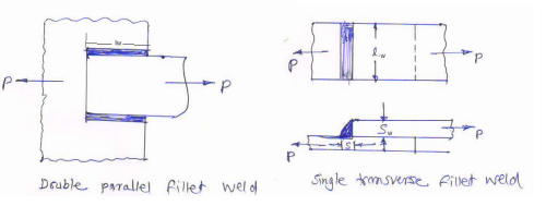
Question:
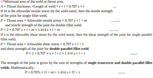
State the strength equation of double parallel fillet weld and single transverse fillet weld with neat sketches Answer:
|
4 |
view |
| Q 6 e ) |
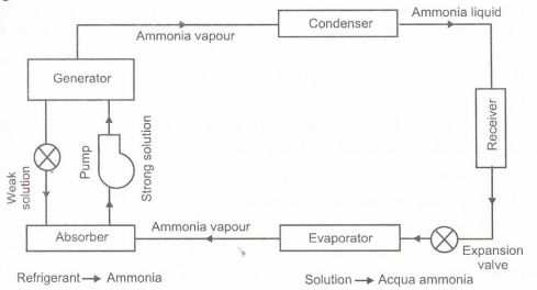
Question:
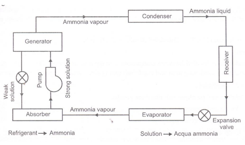
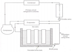
Explain the working of simple vapour absorption refrigeration system. Or Explain with neat sketch vapour absorption refrigeration system. Answer:
|
4 |
view |
| Q 6 f ) |
Question:
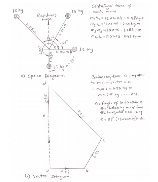
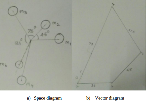
Four masses A, B, C and D are attached to a shaft and revolve in the same plane. The masses are 12 kg, 10 kg, 18 kg and 15 kg respectively and their radii of rotations are 40 mm, 50 mm, 60 mm and 30 mm. The angular position of the masses B, C and D are 60O, 135O ,and 270O from the mass ‘A’. Find the magnitude and position of the balancing mass at a radius of 100 mm. Use graphical method only. Answer:
 |
4 |
view |


| Que.No | Question/Problem | marks | Link |
|---|---|---|---|
| Q 1 a ) |
Question:
Define machine design. Answer:
mechanical elements so that the resultant machine will perform the prescribed task. OR Machine Design is the creation of new and better machines and improving the existing ones |
2 |
view |
| Q 1a)(a) |
Question:
Pappu Define kinematic link and kinematic chain. Answer:
|
2 |
view |
| Q 1a)(a) |
Question:
Define kinematic link and kinematic chain. Answer:
|
2 |
view |
| Q 1a)(a) |
Question:
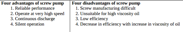
State the four advantages and disadvantages of screw pump. Answer:
 |
4 |
view |
| Q 1a)(a) |
Question:
Draw p-v and T-S diagram for Diesel cycle. Name the processes involved in it. Answer:
|
4 |
view |
| Q 1a)(b) |
Question:
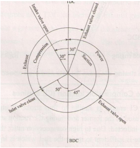
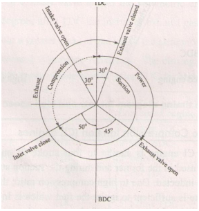
Draw actual valve timing diagram for 4-stroke petrol engine. Answer:
|
4 |
view |
| Q 1a)(b) |
Question:
State types of cams. Answer:
|
2 |
view |
| Q 1a)(b) |
Question:
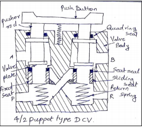
Explain the construction of 4/2 poppet valve with neat sketch & symbol. Answer:
|
4 |
view |
| Q 1a)(c) |
Question:
Classify air compressors Answer:
|
4 |
view |
| Q 1a)(c) |
Question:
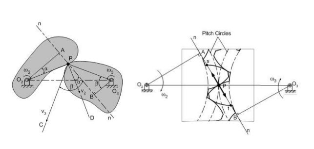
State law of gearing. Answer:
|
2 |
view |
| Q 1a)(c) |
Question:
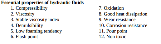
State the essential properties of hydraulic fluids. Answer:
 |
4 |
view |
| Q 1a)(d) |
Question:
Explain any two mounting methods of cylinder. Answer:
|
4 |
view |
| Q 1a)(d) |
Question:
Classify gas turbine on the basis of Answer:
|
4 |
view |
| Q 1a)(d) |
Question:
State the types of chains & sprockets. Answer:
|
2 |
view |
| Q 1a)(e) |
Question:
State the function of flywheel in I.C. Engine. Answer:
|
2 |
view |
| Q 1a)(f) |
Question:
State the function of governor. Answer:
|
2 |
view |
| Q 1a)(g) |
Question:
Compare brakes and dynamometers. (any two points) Answer:
|
2 |
view |
| Q 1a)(h) |
Question:
Why is balancing of rotating parts necessary for high speed engines ? Answer:
|
2 |
view |
| Q 1a)(i) |
Question:
(a) Define : (i) Spherical pair (ii) Higher pair Answer:
|
2 |
view |
| Q 1 b ) |
Question:
Give the composition of :- (i) FeE220: (ii) 20C8 Answer:
|
2 |
view |
| Q 1 b ) |
Question:
(b) Define : (i) Radial follower (ii) Off-set follower Answer:
|
2 |
view |
| Q 1 b ) |
Question:
State any four types of friction clutch, along with its application each. Answer:
|
4 |
view |
| Q 1 b ) |
Question:
Define slip and creep with reference to belt drive. Also state their effect on velocity ratio. Answer:
|
4 |
view |
| Q 1b)(a) |
Question:
Draw general layout of hydraulic system and explain its working. Answer:
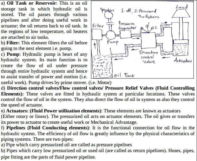 |
6 |
view |
| Q 1b)(a) |
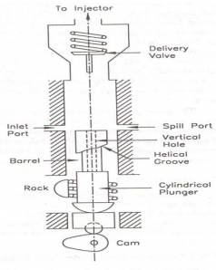
Question:
Draw a neat labelled sketch of fuel injection pump. Give its function. Answer:
|
6 |
view |
| Q 1b)(a) |
Question:
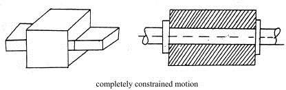
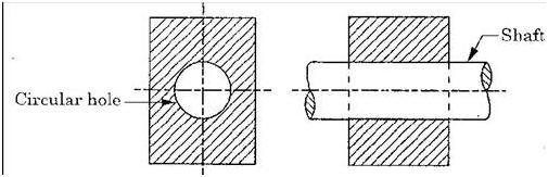
Define completely constrained motion and successfully constrained motion with neat sketch. State one example of each. Answer:
|
4 |
view |
| Q 1b)(b) |
Question:
With a neat sketch explain pressure compensated flow control valve. Draw symbol of it. Answer:
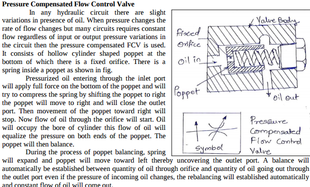 |
6 |
view |
| Q 1b)(b) |
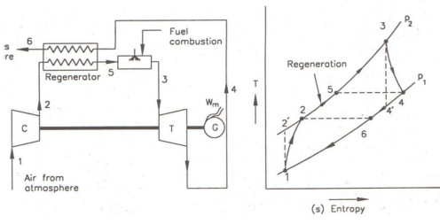
Question:
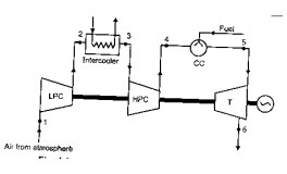
Explain regeneration method to improve thermal efficiency of gas turbine with the help of Answer:
|
6 |
view |
| Q 1b)(b) |
Question:
State function of clutch. Explain working principle of clutch. Answer:
|
4 |
view |
| Q 1b)(ii) |
Question:
2) Define : a) Ductility b) Toughness c) Creep Answer:
|
8 |
view |
| Q 1 c ) |
Question:
State four types of loads acting on machine elements Answer:
|
2 |
view |
| Q 1 c ) |
Question:
What do you mean by crowning of pulleys in flat belt drive ? State its use. Answer:
|
2 |
view |
| Q 1 d ) |
Question:
What do you mean by creep? Answer:
|
2 |
view |
| Q 1 d ) |
Question:
Define initial tension in belt drive & state its effect. Answer:
|
2 |
view |
| Q 1 e ) |
Question:
Define Ergonomics. Answer:
|
2 |
view |
| Q 1 e ) |
Question:
Define fluctuation of speed and fluctuation of energy in case of flywheel. Answer:
|
2 |
view |
| Q 1 f ) |
Question:
Give two applications of knuckle joint. Answer:
|
2 |
view |
| Q 1 f ) |
Question:
Define the sensitivity in relation to governer. State its significance. Answer:
|
2 |
view |
| Q 1 g ) |
Question:
Define following terms of spring: Answer:
known as spring stiffness or spring constant. Mathematically, Spring rate, k = W / δ Where, W = Load δ = Deflection of the spring (ii) Spring index: The spring index is defined as the ratio of the mean diameter of the coil to the diameter of the wire. Mathematically, Spring index, C = D / d Where, D = Mean diameter of the coil d = Diameter of the wire |
2 |
view |
| Q 1 h ) |
Question:
How do you express the life of bearings? Answer:
|
2 |
view |
| Q 1 h ) |
Question:
State the adverse effect of imbalance of rotating elements of machine. Answer:
|
2 |
view |
| Q 1 i ) |
Question:
Draw the different thread profiles used for power screws. Answer:
 |
2 |
view |
| Q 1 j ) |
Question:
State four types of keys. Answer:
|
2 |
view |
| Q 1 k ) |
Question:
Give two examples, where screwed joints are preferred over welded joints. Answer:
|
2 |
view |
| Q 1 l ) |
Question:
State any four applications of rolling contact bearings. Answer:
|
2 |
view |
| Q 1 m ) |
Question:
What are the requirement of a good coupling? Answer:
|
2 |
view |
| Q 1 n ) |
Question:
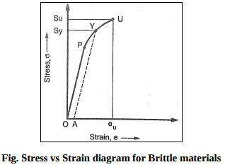
Draw stress – strain diagram for brittle material. Answer:
 |
2 |
view |
| Q 2 a ) |
Question:
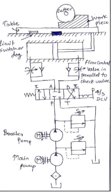
Explain with neat sketch the working of hydraulic circuit for milling machine. Answer:
|
8 |
view |
| Q 2 a ) |
Question:
Reciprocating air compressor draws 6 kg of air per minute at 25°C. It compresses the air Answer:
 |
8 |
view |
| Q 2 a ) |
Question:
Differentiate between machine and structure. Answer:
Machine Structure All parts / links have relative motion No relative motion between the links It transforms the available energy into some useful work No energy transformations The kinematic link of a machine may transmit both power and The member of the structure transmit forces only |
4 |
view |
| Q 2 a ) |
Question:
What is a machine ? Differentiate between a machine and a structure. Answer:
Machine Structure All parts / links have relative motion No relative motion between the links It transforms the available energy into some useful work No energy transformations The kinematic link of a machine may transmit both power and motion The member of the structure transmit forces only Examples: I.C. Engine, Machine tools, steam engine, type writer, etc. Example: Truss of roof, frame of machine, truss of bridge Studied under 'Dynamics' Studied under 'Statics' |
4 |
view |
| Q 2 a ) |
Question:
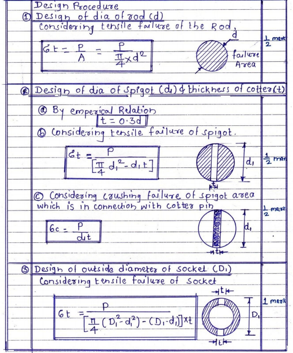
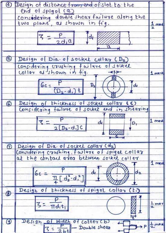
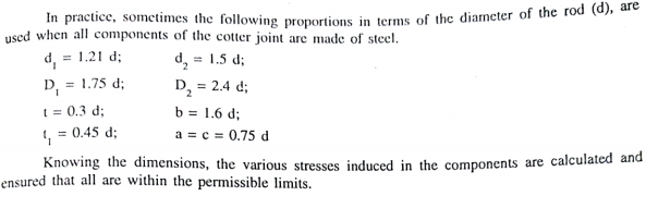
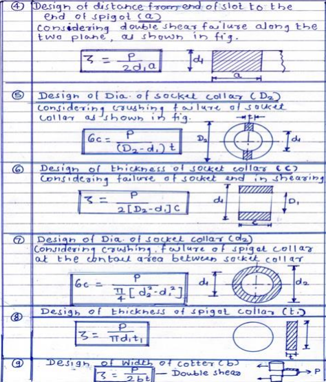
Explain various failures to be considered in designing a cotter joint along with the necessary sketches and strength equations. Answer:
    |
8 |
view |
| Q 2 b ) |
Question:
Name any eight pipe or tube fitting with their application. Answer:
|
8 |
view |
| Q 2 b ) |
Question:
State the theories of elastic failure. Explain maximum normal stress theory and maximum shear stress theory with equations. Or Explain Maximum shear stress theory. {Maximum shear stress theory is also called as?} Answer:
|
8 |
view |
| Q 2 b ) |
Question:
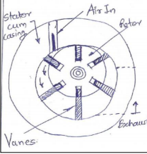
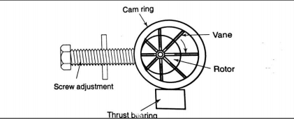
List various types of air motors. Explain vane type air motor with neat sketch. Answer:
|
8 |
view |
| Q 2 b ) |
Question:
Explain with the neat sketch working of crank and slotted lever quick return mechanism. Answer:
|
4 |
view |
| Q 2 b ) |
Question:
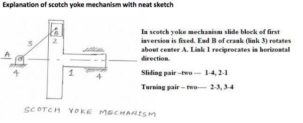
Describe with neat sketch the working of scotch yoke mechanism. Answer:
|
4 |
view |
| Q 2 c ) |
Question:
What is seal ? Classify seals according to shape. State the factors for seal selection. Answer:
|
8 |
view |
| Q 2 c ) |
Question:
The following results were obtained during Morse test on 4-stroke petrol engine. Brake power developed when all cylinders working = 16.2 kW Answer:
 |
8 |
view |
| Q 2 c ) |
Question:
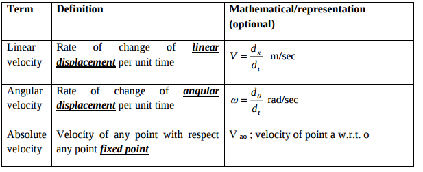
Define linear velocity, angular velocity, absolute velocity and state the relation between linear velocity and angular velocity Answer:
 |
4 |
view |
| Q 2 c ) |
Question:
Explain the inter-relation between linear and angular velocity, linear and angular acceleration with suitable example. Answer:
  |
4 |
view |
| Q 2c)(i) |
Question:
(i) State and describe in brief about four ergonomic considerations in the designing of machine elements. Answer:
|
8 |
view |
| Q 2c)(ii) |
Question:
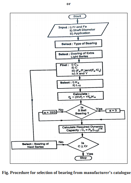
(ii) How will select bearing from manufacturer catalogue? Answer:
|
8 |
view |
| Q 2 d ) |
Question:
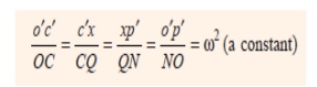
Explain the Klein’s construction to determine velocity and acceleration of single slider crank mechanism Answer:
 |
4 |
view |
| Q 2 d ) |
Question:
Explain the Klein’s construction to determine velocity and acceleration of a link in an I.C. engine mechanism. Answer:
|
4 |
view |
| Q 2 e ) |
Question:
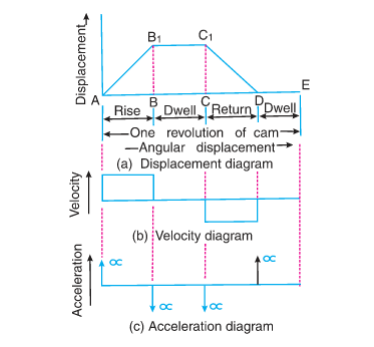
Draw the labelled displacement, velocity and acceleration diagrams for a follower when it moves with simple harmonic motion. Answer:
|
4 |
view |
| Q 2 e ) |
Question:
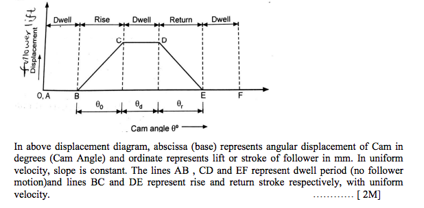
Draw the labelled displacement, velocity and acceleration diagrams for a follower when it moves with uniform velocity. Answer:
 |
4 |
view |
| Q 2 f ) |
Question:
A pulley rotating at 50 m/s transmits 40 kW. The safe pull in belt is 400 N/cm width of belt. The angle of lap is 170º. If coefficient of friction is 0.24, find required width of belt. Answer:
|
4 |
view |
| Q 2 f ) |
Question:
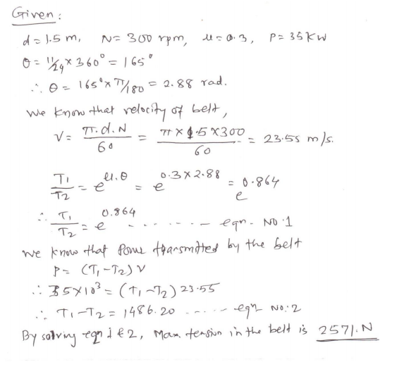
A flat belt drive is required to transmit 35 kW from a pulley of 1.5 m effective diameter running at speed of 300 rpm. The angle of contact is spread over 11/24 of the circumference co-efficient of friction for the surface is 0.3. Determine the maximum tension in the belt. Answer:
 |
4 |
view |
| Q 3 ) |
Question:
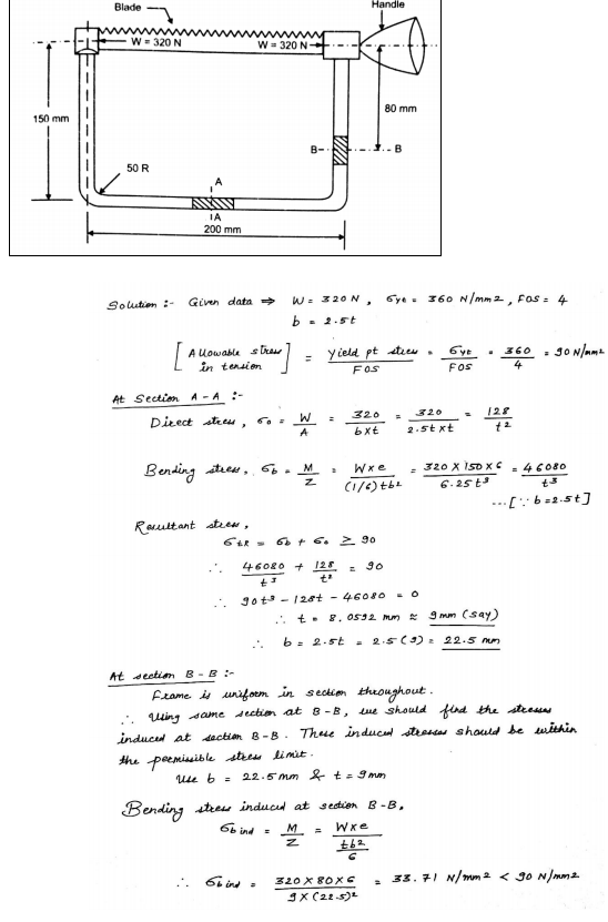
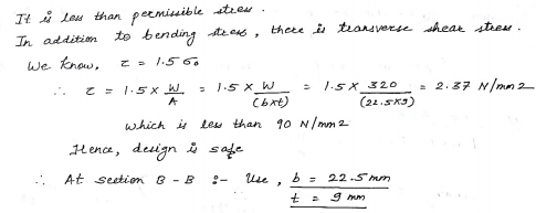
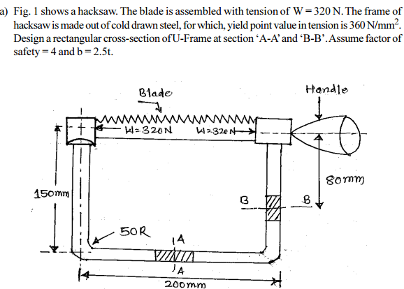
Fig.1Show of hacksaw The belt is assembled with tensoion
Answer:
  |
8 |
view |
| Q 3 a ) |
Question:
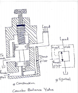
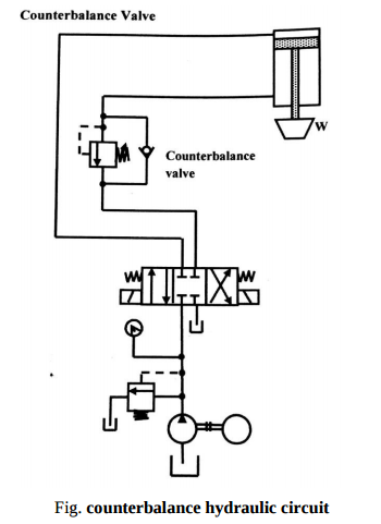
Explain the working of counter balance valve in hydraulic circuit. Answer:
|
4 |
view |
| Q 3 a ) |
Question:
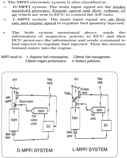
Explain MPFI with neat sketch. Answer:
|
4 |
view |
| Q 3 a ) |
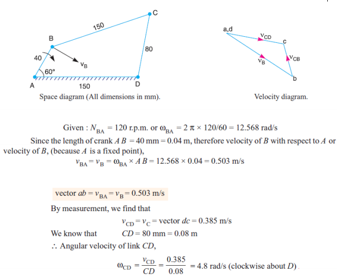
Question:
In a four bar chain ABCD, AD is fixed and is 150 mm long. The crank AB is 40 mm long and rotates at 120 r.p.m. clockwise, while the link CD = 80 mm oscillates about D. BC and AB are of equal length. Find the angular velocity of link CD when angle BAD = 60. Answer:
 |
4 |
view |
| Q 3a)(i) |
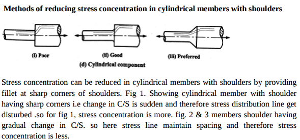
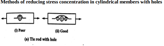
Question:
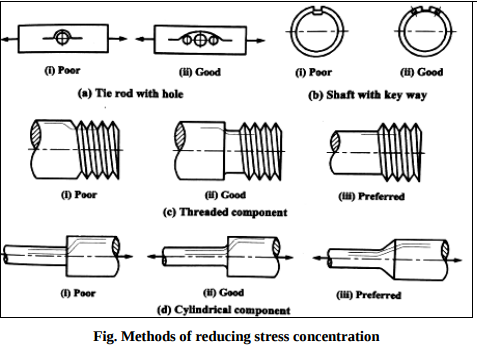
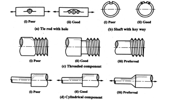
Explain with neat sketches only (i) Methods of reducing stress concentration in cylindrical members with shoulders. (ii) Methods of reducing stress concentration in cylindrical members with holes.
Answer:
  |
4 |
view |
| Q 3 b ) |
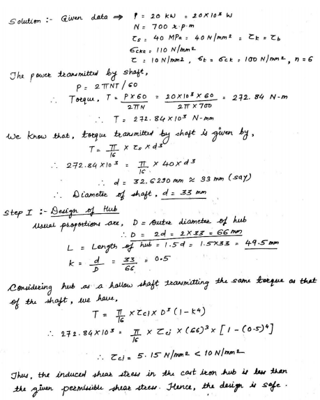
Question:
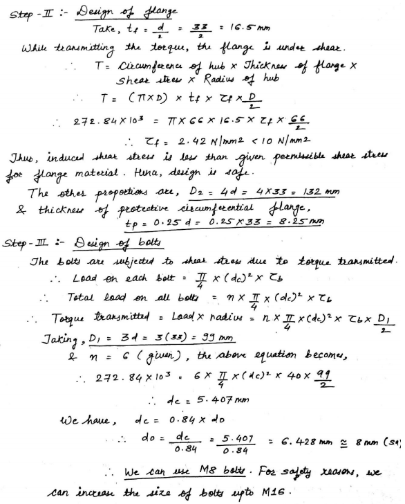
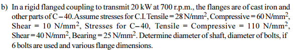
In a rigid flaninged complended to transmit 20K.W at 700.r.p.m
Answer:
  |
8 |
view |
| Q 3 b ) |
Question:
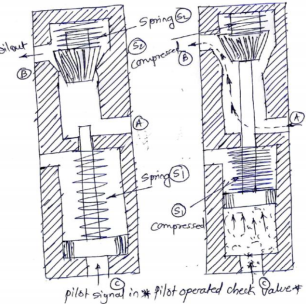
Discuss pilot operated check valve with neat sketch. Answer:
|
4 |
view |
| Q 3 b ) |
Question:
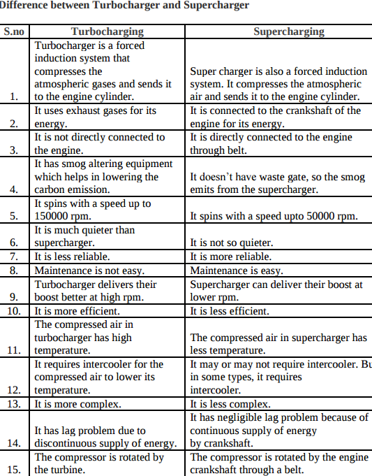
Differentiate supercharging and turbocharging in I.C. engine. Answer:
 |
4 |
view |
| Q 3 b ) |
Question:
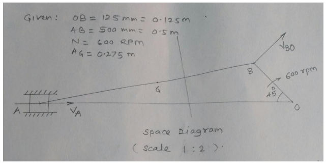
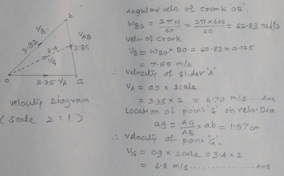
In a slider crank mechanism, the length of crank OB and connecting rod AB are 125 mm and 500 mm respectively. The centre of gravity G of the connecting rod is 275 mm from the slider. The crank speed is 600 rpm clockwise. When the crank has turned 45 from the inner dead centre position, determine : (i) Velocity of slider ‘A’, (ii) Velocity of the point ‘G’ graphically. Answer:
  |
4 |
view |
| Q 3 c ) |
Question:
Define stress concentration. What are the causes of stress concentration? State any four methods of reducing stress concentration with neat sketches. Answer:
|
8 |
view |
| Q 3 c ) |
Question:
What are the considerations in design of dimensions of formed and parallel key having rectangular cross section?
Answer:
 |
4 |
view |
| Q 3 c ) |
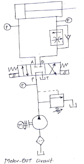
Question:
Explain with neat sketch the working of meter out hydraulic circuit. Answer:
|
4 |
view |
| Q 3 c ) |
Question:
State the advantages of lubricant additives (any four). Answer:
|
4 |
view |
| Q 3 c ) |
Question:
Explain slip and creep phenomenon in belts. Answer:
|
4 |
view |
| Q 3 d ) |
Question:
Draw the neat sketch of diaphragm clutch and explain its working. Answer:
|
4 |
view |
| Q 3 d ) |
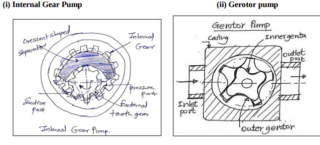
Question:
Draw neat labelled sketch of (i) Internal gear pump (ii) Gerotor pump Answer:
 |
4 |
view |
| Q 3 d ) |
Question:
Explain the working principle of turbojet with neat sketch. Answer:
|
4 |
view |
| Q 3 e ) |
Question:
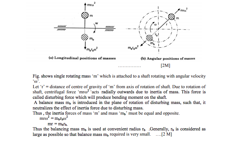
Write the procedure for balancing of a single rotating mass by single masses rotating in the same plane. Answer:
|
4 |
view |
| Q 3 e ) |
Question:
What is FRL ? State the function of each component of FRL. Answer:
|
4 |
view |
| Q 3 e ) |
Question:
State the advantages of closed cycle gas turbine over open cycle gas turbine (any four). Answer:
|
4 |
view |
| Q 3 f ) |
Question:
Give detailed classification of followers. Answer:
|
4 |
view |
| Q 4 a ) |
Question:
State advantages and disadvantages of chain drive over belt drive Answer:
|
4 |
view |
| Q 4 a ) |
Question:
Fig 2 show a C.I. bracket to carryof a shaft
Answer:
 |
8 |
view |
| Q 4a)(a) |
Question:
State the four merits and demerits of using a rubber hose in pneumatic circuit. Answer:
|
4 |
view |
| Q 4a)(a) |
Question:
Define the following w.r.to. I.C. engine. Answer:
|
4 |
view |
| Q 4a)(b) |
Question:
List any four applications of pneumatic rotary actuator. Draw the symbol for variable speed bidirectional air motor. Answer:
|
4 |
view |
| Q 4a)(b) |
Question:
Explain the term swept volume (V s ) w.r.to. Answer:
|
4 |
view |
| Q 4a)(c) |
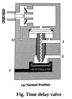
Question:
What is the Function of Time Delay valve? Answer:
|
4 |
view |
| Q 4a)(c) |
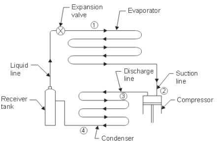
Question:
Draw a neat block diagram of vapour compression cycle. Show the direction of flow ofrefrigerant. Answer:
|
4 |
view |
| Q 4a)(d) |
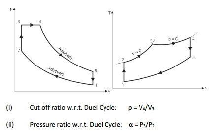
Question:
Explain w.r.to. dual cycle i) cutoff ratio ii) pressure ratio. Answer:
|
4 |
view |
| Q 4a)(d) |
Question:
Draw speed control pneumatic circuit for bi-directional air motor. Answer:
|
4 |
view |
| Q 4 b ) |
Question:
Justify that slider crank mechanism is a modification of the basic four bar mechanism with neat sketch. Answer:
|
4 |
view |
| Q 4 b ) |
Question:
A helical compeersion imperssion speraing
Answer:
 |
8 |
view |
| Q 4b)(a) |
Question:
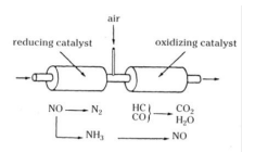
What is meant by catalytic converter ? Briefly explain with the help of neat sketch. Answer:
|
6 |
view |
| Q 4b)(a) |
Question:
Explain variable displacement axial piston pump with neat sketch. Answer:
 |
6 |
view |
| Q 4b)(b) |
Question:
Explain working of counterbalance hydraulic circuit with neat diagram. Answer:
|
6 |
view |
| Q 4b)(b) |
Question:
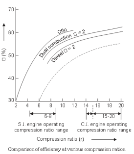
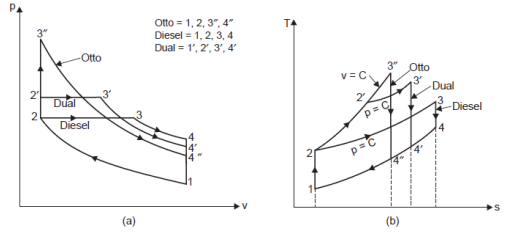
Draw superimposed p-v diagram of Otto cycle, Diesel cycle and Dual cycle to compare Answer:
|
6 |
view |
| Q 4 c ) |
Question:
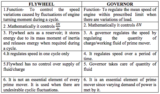
Compare flywheel and governor. Answer:
|
4 |
view |
| Q 4 c ) |
Question:
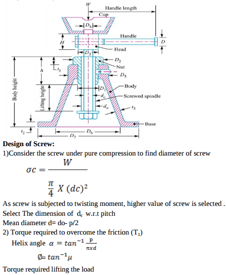
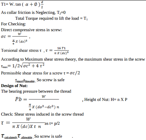
Design of screw jack
Answer:
  |
8 |
view |
| Q 4 d ) |
Question:
Explain with neat sketch construction and working of eddy current dynamometer. Answer:
|
4 |
view |
| Q 4 e ) |
Question:
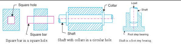
A flat foot step bearing 225 mm in diameter supports a load of 7500 N. If the co-efficient of friction is 0.09 and the shaft rotates at 600 rpm, calculate the power lost in friction. Answer:
|
4 |
view |
| Q 4 f ) |
Question:
Four masses attached to a shaft and their respective radii of rotation are given as : Answer:
|
4 |
view |
| Q 5 a ) |
Question:
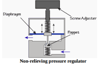
List different types of pressure regulator valves ? Explain any one with neat sketch. Answer:
|
8 |
view |
| Q 5 a ) |
Question:
State the methods to improve efficiency of air compressor. Explain two stage air compressor with perfect intercooling with neat sketch. Answer:
|
8 |
view |
| Q 5 a ) |
Question:
The crank of a slider crank mechanism rotates clockwise at a constant speed Answer:
  |
8 |
view |
| Q 5 a ) |
Question:
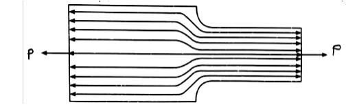
Parallel and transverse Weld
Answer:
 |
8 |
view |
| Q 5 b ) |
Question:
Develop a pneumatic circuit for operation of two DA cylinders such that one operates after other using travel dependant sequencing. Answer:
 |
8 |
view |
| Q 5 b ) |
Question:
State the applications of reciprocating compressor and rotary compressor (4 each). Answer:
|
8 |
view |
| Q 5 b ) |
Question:
Draw the profile of a cam to raise a valve with S.H.M. through 40 mm in Answer:
|
8 |
view |
| Q 5 b ) |
Question:
Power Screw: Given Data
Answer:
|
8 |
view |
| Q 5 c ) |
Question:
Explain pneumatic impulse circuit with neat sketch. Answer:
|
8 |
view |
| Q 5 c ) |
Question:
List out different pollutants in exhaust gases of petrol and diesel engine ? Briefly explain theireffects on human beings and environments (atleast four). Answer:
|
8 |
view |
| Q 5 c ) |
Question:
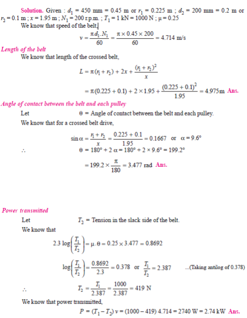
Two pulley, one 450 mm diameter and the other 200 mm diameter are on Answer:
 |
8 |
view |
| Q 5 c ) |
Question:
Hollow shaft:
Answer:
  |
8 |
view |
| Q 6 a ) |
Question:
State at least four advantages and disadvantages of pneumatic systems. Answer:
|
4 |
view |
| Q 6 a ) |
Question:
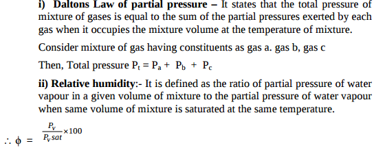
Explain the following terms :- i) Daltons law of partial pressures ii) Relative humidity Answer:
 |
4 |
view |
| Q 6 a ) |
Question:
Effect of Keyway on strength of shaft
Answer:
  |
8 |
view |
| Q 6a)(i) |
Question:
State types of gear train and explain any one. Answer:
|
8 |
view |
| Q 6a)(ii) |
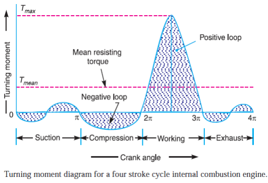
Question:
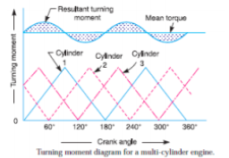
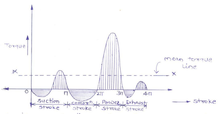
Draw turning moment diagram for single cylinder four stroke I.C. Answer:
|
8 |
view |
| Q 6 b ) |
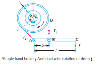
Question:
A simple band brake is operated by lever 40 cm long. The brake drum Answer:
|
8 |
view |
| Q 6 b ) |
Question:
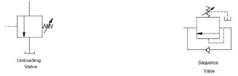
Draw symbol of unloading valve and sequence valve. Answer:
 |
4 |
view |
| Q 6 b ) |
Question:
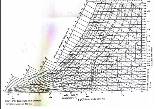
Sketch a psychrometric chart and show the following properties of air on it. i) DBT lines ii) WBT lines iii) Specific volume lines iv) Relative humidity lines Answer:
 |
4 |
view |
| Q 6b)(i) |
Question:
Identyfiy the metrial and its compotion A) X10Cr 18 Ni9 Mo 4 Si 2 B) XT72W18Cr4V1:
Answer:
|
8 |
view |
| Q 6b)(ii) |
Question:
Design consideration while designing the spur Gear Answer:
|
8 |
view |
| Q 6 c ) |
Question:
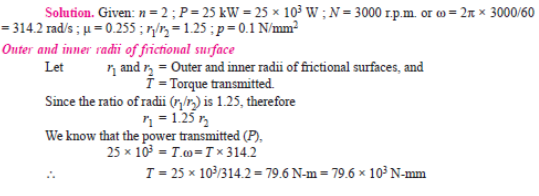
A single plate clutch, effective on both sides, is required to transmit 25 kW at Answer:
  |
8 |
view |
| Q 6 c ) |
Question:
Enlist the hydraulic oil manufacturer’s in India. Answer:
|
4 |
view |
| Q 6 c ) |
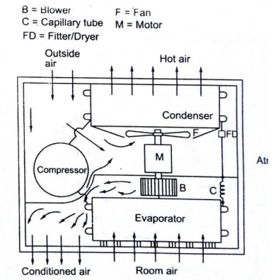
Question:
Draw only a neat labelled sketch of window air-conditioner. Answer:
|
4 |
view |
| Q 6c)(i) |
Question:
State any four area of Application of spring: Answer:
|
4 |
view |
| Q 6c)(ii) |
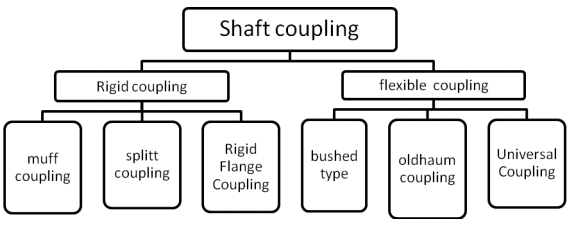
Question:
State of the Classification of shaft coupling : Answer:
 |
8 |
view |
| Q 6 d ) |
Question:
Enlist applications of hydraulic system. Answer:
|
4 |
view |
| Q 6 d ) |
Question:
Enlist different uses of compressed air. Answer:
|
4 |
view |
| Q 6 e ) |
Question:
Explain pneumatic circuit for speed control of single acting cylinder with neat sketch. Answer:
 |
4 |
view |
| Q 6 e ) |
Question:
State the applications of gas turbine (any four). Answer:
|
4 |
view |

.png)

| Que.No | Question/Problem | marks | Link | |||||||||||||||
|---|---|---|---|---|---|---|---|---|---|---|---|---|---|---|---|---|---|---|
| Q a)(ii) |
Question:
Explain single cylinder 4-stroke I.C. engine using turning moment diagram. Answer:
|
4 |
view | |||||||||||||||
| Q 1a)(a) |
Question:
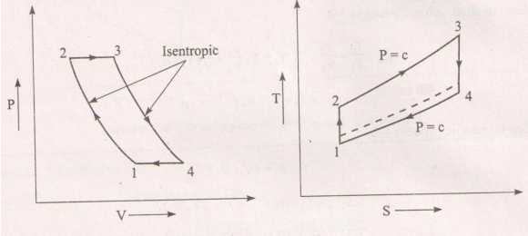
Represent ‘Brayton Cycle’ on P-V and T-S diagram. Answer:
 |
4 |
view | |||||||||||||||
| Q 1a)(b) |
Question:
Define following terms w.r.t. air compressor. i) FAD ii) Compression ratio. Answer:
|
4 |
view | |||||||||||||||
| Q 1a)(c) |
Question:
Enlist different uses of compressed air. Answer:
|
4 |
view | |||||||||||||||
| Q 1a)(d) |
Question:
Draw ‘Valve timing diagram for 4-stroke cycle diesel engine. Answer:
 |
4 |
view | |||||||||||||||
| Q 1a)(i) |
Question:
Enlist the types of constrained motion. Draw a label sketch of any one Answer:
(i)Completely constrained motion. (ii)Incompletely constrained motion. (iii)Successfully constrained motion. |
2 |
view | |||||||||||||||
| Q 1a)(ii) |
Question:
Define (i) Pressure angle (ii) Pitch point related to cam. Answer:
(ii) Pitch point: It is point on pitch curve having the maximum pressure angle. |
2 |
view | |||||||||||||||
| Q 1a)(iii) |
Question:
How are drives classified? Answer:
(i) Belt drives. (ii) Chain drives. (iii) Rope. (iv) Gear drives. |
2 |
view | |||||||||||||||
| Q 1a)(iv) |
Question:
Define: Answer:
Mathematically, C s = (N 1 – N 2 ) /N Where, N 1 = maximum speed in rpm; Mathematically, Ce = Maximum fluctuation of energy/ Work done per cycle. |
2 |
view | |||||||||||||||
| Q 1a)(v) |
Question:
Write any two disadvantages of chain drive. Answer:
1. Manufacturing cost of chains is relatively high. 2. The chain drive needs accurate mounting and careful maintenance. 3. High velocity fluctuations especially when unduly stretched. 4. Chain operations are noisy as compared to belts. |
2 |
view | |||||||||||||||
| Q 1a)(vi) |
Question:
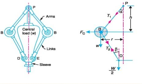
Draw line diagram of porter governor Answer:
 |
2 |
view | |||||||||||||||
| Q 1a)(vii) |
Question:
State the application of (i) Disc brake (ii) Internal expanding brake Answer:
(ii) Internal expanding brake: Used in motor cars, light trucks, two wheelers etc. |
2 |
view | |||||||||||||||
| Q 1a)(viii) |
Question:
Why is balancing of rotating parts necessary for high speed engines? Answer:
is, therefore, very essential that all the rotating and reciprocating parts should be completely balanced as far as possible. If these parts are not properly balanced, the dynamic forces are set up. These forces not only increase the loads on bearings and stresses in the various members, but also produce unpleasant and even dangerous vibrations. The balancing of unbalanced forces is caused by rotating masses, in order to minimize pressure on the main bearings when an engine is running. |
2 |
view | |||||||||||||||
| Q 1b)(a) |
Question:
Explain in brief, how ‘Morse test’ is carried out ? Answer:
|
6 |
view | |||||||||||||||
| Q 1b)(b) |
Question:
Explain with neat sketch the constructional features of ‘Three Way Catalytic Converter’. Answer:
 |
6 |
view | |||||||||||||||
| Q 1b)(i) |
Question:
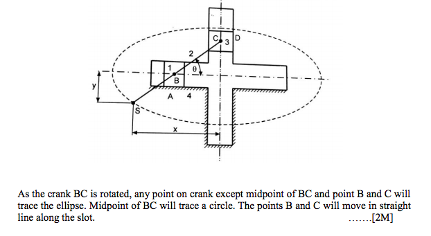
State inversions of double slider crank chain. Explain Oldham's coupling with neat sketch Answer:
i.Scotch Yoke mechanism. ii.Oldham’s coupling. iii. Elliptical trammel. An Oldham’s coupling is used for connecting two parallel shafts whose axes are at a small distance apart. The shafts are coupled in such a way that if one shaft rotates, the other shaft also rotates at the same speed. This inversion is obtained by fixing the link 2, as shown in Fig. The shafts to be connected have two flanges (link 1 and link 3) rigidly fastened at their ends by forging. The link 1 and link 3 form turning pairs with link 2. These flanges have diametrical slots cut in their inner faces, as shown in Fig. The intermediate piece (link 4) which is a circular disc, have two tongues (i.e. diametrical projections) T1 and T2 on each face at right angles to each other. The tongues on the link 4 closely fit into the slots in the two flanges (link 1 and link 3). The link 4 can slide or reciprocate in the slots in the flanges. (link 4) to rotate at the same angle through\ which the flange has rotated, and it further rotates the flange D (link 3) at the same angle and thus the shaft B rotates. Hence links 1, 3 and 4 have the same angular velocity at every instant. A little consideration will show that there is a sliding motion between the link 4 and each of the other links 1 and 3. |
4 |
view | |||||||||||||||
| Q 1b)(ii) |
Question:
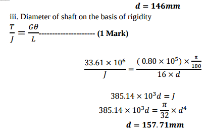
The shaft running at 125 r.p.m. transmits 440 kW. Find the diameter of shaft (d) if allowable shear stress in shaft material is 55 N/mm2 and the angle of twist must not be more than 1 on a length of 16(d). The modulus of rigidity G = 0.80 105 N/mm Answer:
 |
6 |
view | |||||||||||||||
| Q 1b)(ii) |
Question:
Explain: (i) Uniform pressure theory. (ii) Uniform wear theory in clutches and bearing. Answer:
When the mating component in clutch, bearing are new, then the contact between surfaces may be good over the whole surface. It means that the pressure over the rubbing surfaces is uniform distributed. This condition is not valid for old clutches, bearings because mating surfaces may have uneven friction. The condition assumes that intensity of pressure is same. P = W/A =Constant; where, W= load, A= area (ii) Uniform wear theory in clutches and bearings: parts of the rubbing surfaces will not move with the same velocity. The velocity of rubbing surface increases with the distance from the axis of the rotating element. It means that wear may be different at different radii and rate of wear depends upon the intensity of pressure (P) and the velocity of rubbing surfaces (V). It is assumed that the rate of wear is proportional to the product of intensity of pressure and velocity of rubbing surfaces. This condition assumes that rate of wear is uniform; P*r = Constant; where, P = intensity of pressure, r = radius of rotation. |
4 |
view | |||||||||||||||
| Q 1b)(iii) |
Question:
Compare cross belt drive and open belt drive on the basis of: (i) Velocity ratio. (ii) Direction of driven pulley. (iii) Length of belt drives (iv) Application. Answer:
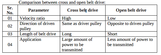 |
4 |
view | |||||||||||||||
| Q 1b)(l) |
Question:
What is stress concentration ? State the remedial measures to control the effect of stress concentration with neat sketches Answer:
|
6 |
view | |||||||||||||||
| Q 1 i ) |
Question:
Draw stress-strain diagram for ductile material stating salient points Answer:
|
4 |
view | |||||||||||||||
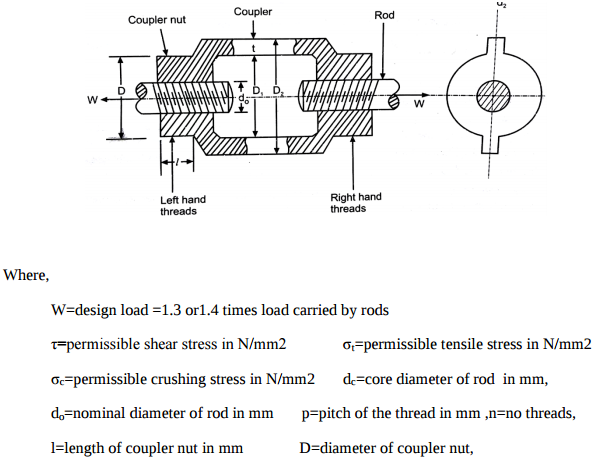
| Q 1 ii ) |
Question:
Write the design procedure for turn buckle. (Any four steps) Answer:
|
4 |
view | |||||||||||||||
| Q 1 iii ) |
Question:
State any four factors to be considered while selecting the coupling. Answer:
|
4 |
view | |||||||||||||||
| Q 1 iv ) |
Question:
Why square threads are preferred over V-thread for power transmission ? Answer:
|
4 |
view | |||||||||||||||
| Q 2 a ) |
Question:
It is desired to compress 15 m3 of air per minute from 1.0132 bar to 10 bar. Calculate minimum power required to drive the compressor having two stages and compared it the power required for single stage compression. Assume value of index for compression process to be 1.3 for both cases also assume the condition for maximum efficiency Answer:
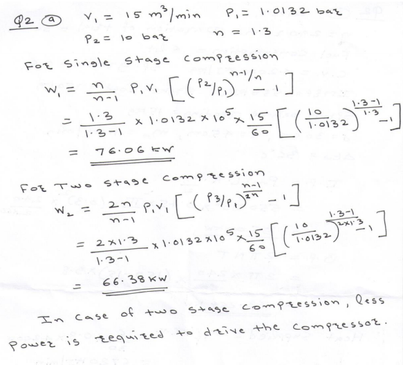 |
8 |
view | |||||||||||||||
| Q 2 a ) |
Question:
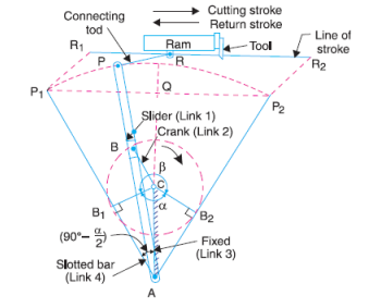
Draw a labeled sketch of quick return mechanism of shaper and explain its working? Answer:
|
4 |
view | |||||||||||||||
| Q 2a)(i) |
Question:
State any four factors that govern ‘factor of safety’. Answer:
|
8 |
view | |||||||||||||||
| Q 2a)(ii) |
Question:
Why taper is provided on cotter ? State recommended values of taper. Answer:
|
8 |
view | |||||||||||||||
| Q 2 b ) |
Question:
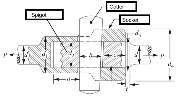
Draw neat sketch showing the details of cotter joint. State strength equations for each component with suitable failure cross-sectional area. Answer:
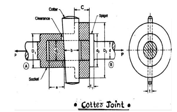 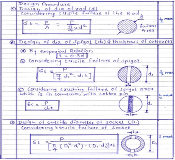  |
8 |
view | |||||||||||||||
| Q 2 b ) |
Question:
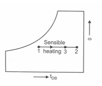
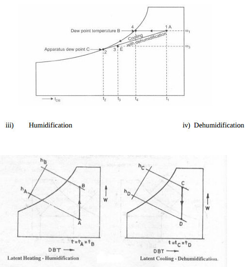
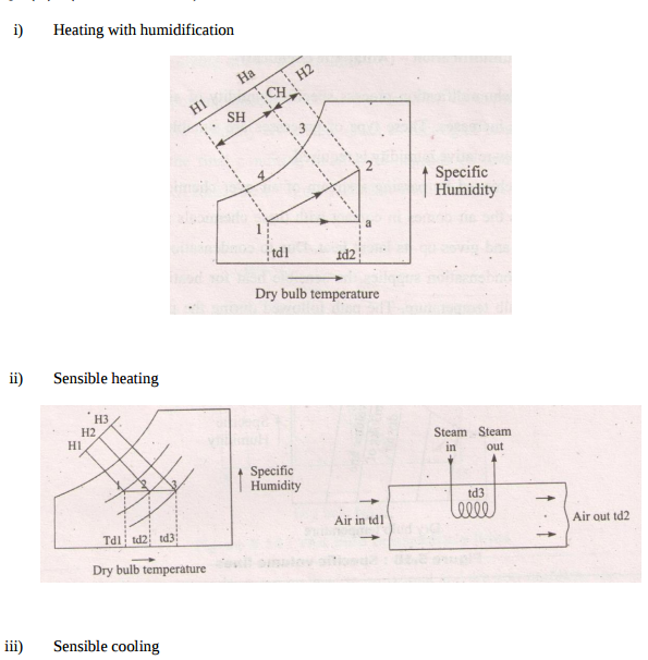
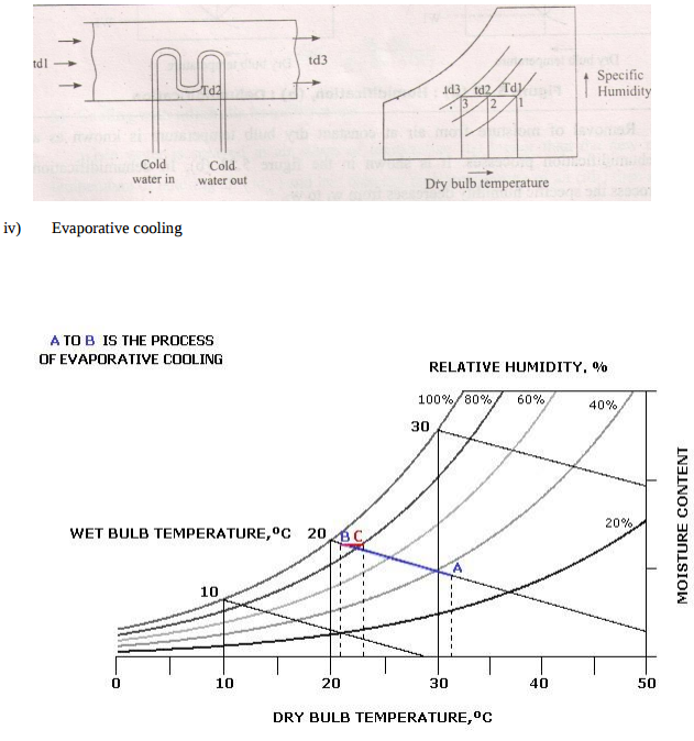
Represent following processes on Psychrometric chart. i) Heating with humidification ii) Sensible heating. iii) Sensible cooling iv) Evaporative cooling. Answer:
  |
8 |
view | |||||||||||||||
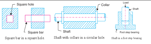
| Q 2 b ) |
Question:
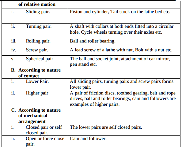
What are the types of kinematic pair ? Give its examples. Answer:
  |
4 |
view | |||||||||||||||
| Q 2 c ) |
Question:
Define linear velocity, angular velocity, absolute velocity and state the relation between linear velocity and angular velocity. Answer:
|
4 |
view | |||||||||||||||
| Q 2 c ) |
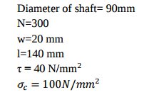
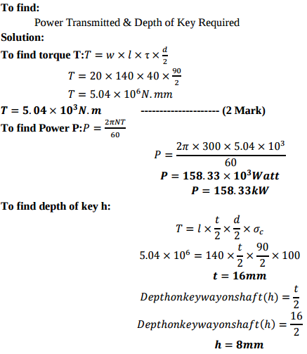
Question:
A belt pulley is fastened to a 90 mm diameter shaft running at 300 r.p.m. by means of a key 20 mm wide and 140 mm long. Allowable stress for the shaft and key material are 40 N/mm2 in shear and 100 N/mm2 in crushing. Find the power transmitted and the depth of the key required. Answer:
  |
8 |
view | |||||||||||||||
| Q 2 c ) |
Question:
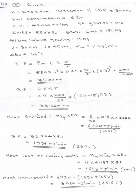
Following observations were made during a trial on 4-stroke, single cylinder engine running at 240 rpm having brake wheel diameter 1.5 meter. Duration of trial 30 min. Fuel consumption 6 liter C.V. of fuel 42000 kJ/kg Sp. gravity 0.8 IMEP 550 kPa Brake load 150 kg Spring balance reading 15 kg Cylinder diameter 30 cm Stroke length 45 cm Jacket cooling water 11 kg/min Temp. rise in jacket water 36°C Determine : i) I.P. and B.P. ii) Heat balance sheet on percentage basis. Answer:
   |
8 |
view | |||||||||||||||
| Q 2 d ) |
Question:
Explain the Klein's construction to determine velocity and acceleration of single slider crank mechanism. Answer:
   |
4 |
view | |||||||||||||||
| Q 2 e ) |
Question:
Draw neat sketch of radial cam with follower and show on it (i) Base circle. (ii) Pitch point. (iii) Prime Circle. (iv) Cam profile Answer:
 |
4 |
view | |||||||||||||||
| Q 2 f ) |
Question:
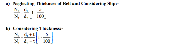
A shaft runs at 80 rpm & drives another shaft at 150 rpm through belt drive. The diameter of the driving pulley is 600 mm. Determine the diameter of the driven pulley in the following cases: (i) Taking belt thickness as 5 mm. (ii) Assuming for belt thickness 5 mm and total slip of 4%. Answer:
|
4 |
view | |||||||||||||||
| Q 3 a ) |
Question:
State any four advantages of standardization. Answer:
|
4 |
view | |||||||||||||||
| Q 3 a ) |
Question:
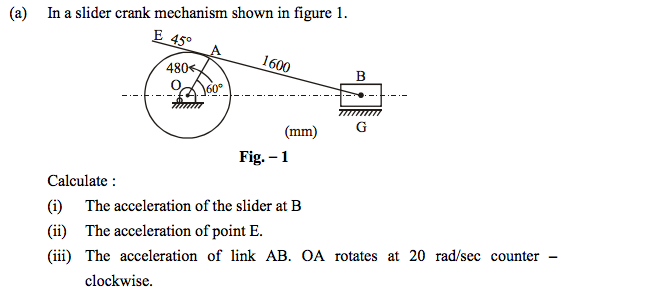
In a slider-crank mechanism, the crank is 480 mm long and rotates at 20 rad/sec in the counter-clockwise direction. The length of the connecting rod is 1600 mm. when the crank turns 60 from the inner-dead centre. Determine the velocity of the slider by relative velocity method. Answer:
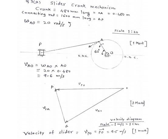 |
4 |
view | |||||||||||||||
| Q 3 b ) |
Question:
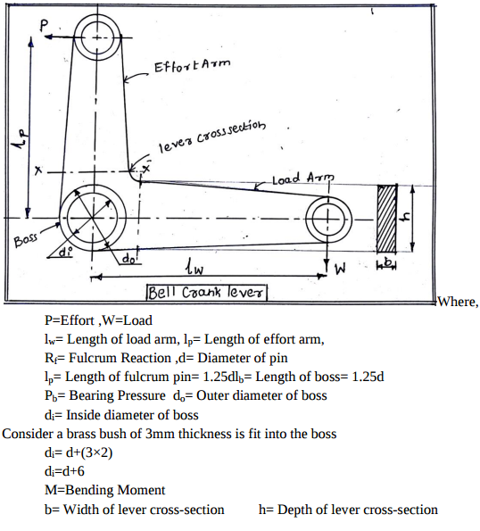
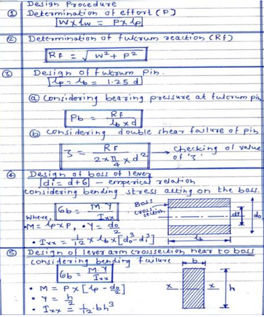
Draw a neat sketch of bell crank lever. Enlist steps in designing the bell crank lever Answer:
  |
4 |
view | |||||||||||||||
| Q 3 b ) |
Question:
Classify gas turbine on the basis of i) working cycle ii) application iii) cycle of operation iv) fuel used Answer:
|
4 |
view | |||||||||||||||
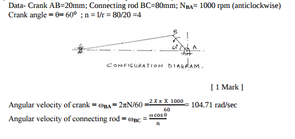
| Q 3 b ) |
Question:
In a slider crank mechanism, crank AB = 20 mm & connecting rod BC = 80 mm. Crank AB rotates with uniform speed of 1000 rpm in anticlockwise direction. Find (i) Angular velocity of connecting rod BC (ii) Velocity of slider C. When crank AB makes an angle of 60 degrees with the horizontal. Draw the configuration diagram also. Use analytical method. Answer:
  |
4 |
view | |||||||||||||||
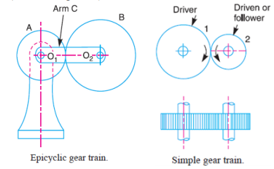
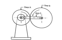
| Q 3 c ) |
Question:
Explain epicyclic gear train with neat sketch. Answer:
 |
4 |
view | |||||||||||||||
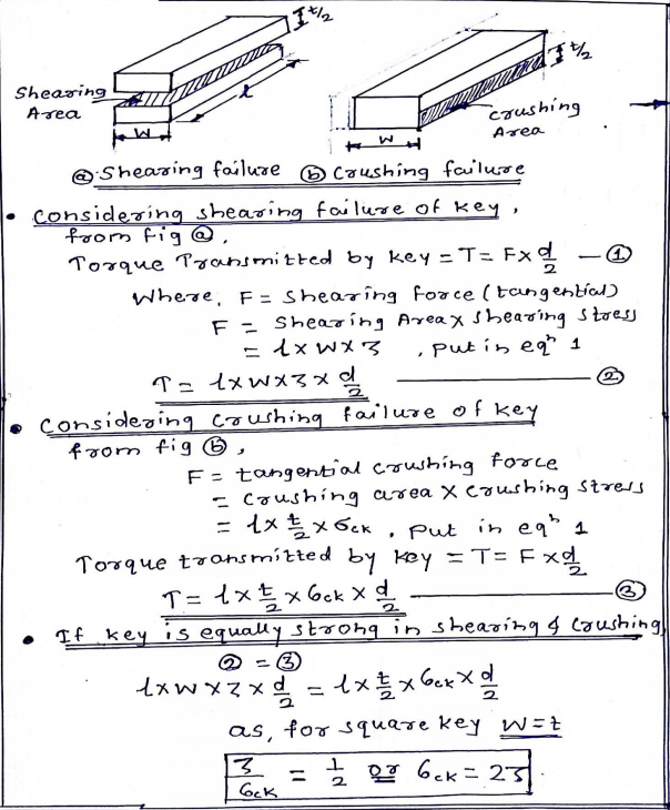
| Q 3 c ) |
Question:
Prove that, for a square key, the permissible crushing stress is twice the permissible shear stress. Answer:
 |
4 |
view | |||||||||||||||
| Q 3 c ) |
Question:
Enlist the four effects of subcooling on the performance of V.C.C. refrigeration cycle. Answer:
 |
4 |
view | |||||||||||||||
| Q 3 d ) |
Question:
Draw a labelled sketch of multiplate clutch and state its applications. Answer:
 |
4 |
view | |||||||||||||||
| Q 3 d ) |
Question:
Why a coupling should be placed as close to a bearing as possible Answer:
|
4 |
view | |||||||||||||||
| Q 3 d ) |
Question:
What is ‘Scavenging’ ? List any two types of ‘scavenging’. Answer:
|
4 |
view | |||||||||||||||
| Q 3 e ) |
Question:
Write the procedure of balancing single rotating mass when it balance mass is rotating in the same plane as that of disturbing mass. Answer:
 |
4 |
view | |||||||||||||||
| Q 3 e ) |
Question:
Describe ‘bolt of uniform strength’ with neat sketch Answer:
|
4 |
view | |||||||||||||||
| Q 3 e ) |
Question:
Explain in brief the importance of ‘Super Charging’. Answer:
|
4 |
view | |||||||||||||||
| Q 3 f ) |
Question:
What are the different types of follower motion ? Also draw displacement diagram for uniform velocity. Answer:
|
4 |
view | |||||||||||||||
| Q 4a)(a) |
Question:
Explain in brief the constructional features of MPFI engine Answer:
|
4 |
view | |||||||||||||||
| Q 4a)(b) |
Question:
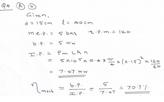
An engine has piston diameter 15 cm, length of stroke 40 cm and mean effective pressure 5 bar. Engine makes 120 power strokes per minute. Find mechanical efficiency if brake power is 5 kW. Answer:
 |
4 |
view | |||||||||||||||
| Q 4a)(c) |
Question:
State any four effect of detonation Answer:
|
4 |
view | |||||||||||||||
| Q 4a)(d) |
Question:
Explain the term w.r.t. I.C. engine. i) Mean Effective Pressure (MEP) ii) Cut off ratio. Answer:
|
4 |
view | |||||||||||||||
| Q 4a)(i) |
Question:
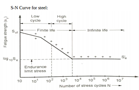
Define Endurance limit and draw typical S-N curve for steel. Answer:
|
4 |
view | |||||||||||||||
| Q 4a)(ii) |
Question:
State the effect of key-way on the strength of shaft with suitable diagram Answer:
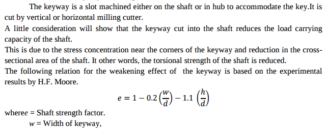 + + |
4 |
view | |||||||||||||||
| Q 4a)(iii) |
Question:
State any four applications of spring. Answer:
|
4 |
view | |||||||||||||||
| Q 4a)(iii) |
Question:
State any four advantages and disadvantages of welded joints over riveted joints. Answer:
|
4 |
view | |||||||||||||||
| Q 4 b ) |
Question:
Justify with neat sketch elliptical trammel as an inversion of double slider crank chain. Answer:
|
4 |
view | |||||||||||||||
| Q 4b)(a) |
Question:
Name any four additives used in lubricants ? State their advantages Answer:
|
6 |
view | |||||||||||||||
| Q 4b)(b) |
Question:
A petrol engine working on constant volume cycle has compression ratio of 8 and consume 1 kg of air per minute, if minimum and maximum temp. during cycle is 300 °K and 2000 °K respectively. Find power developed by engine. Assume γ = 1.4 and Cv = 0.71 kJ/kg °K. Answer:
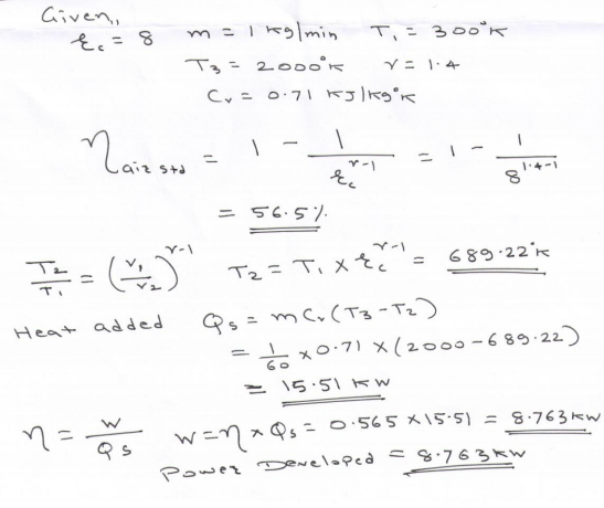 |
6 |
view | |||||||||||||||
| Q 4b)(i) |
Question:
Describe the importance of aesthetic considerations in design related to shape, colour and surface finish. Answer:
|
6 |
view | |||||||||||||||
| Q 4b)(ii) |
Question:
State any six design considerations while designing the spur gear Answer:
|
6 |
view | |||||||||||||||
| Q 4 c ) |
Question:
Differentiate between flywheel and governor. Answer:
|
4 |
view | |||||||||||||||
| Q 4 d ) |
Question:
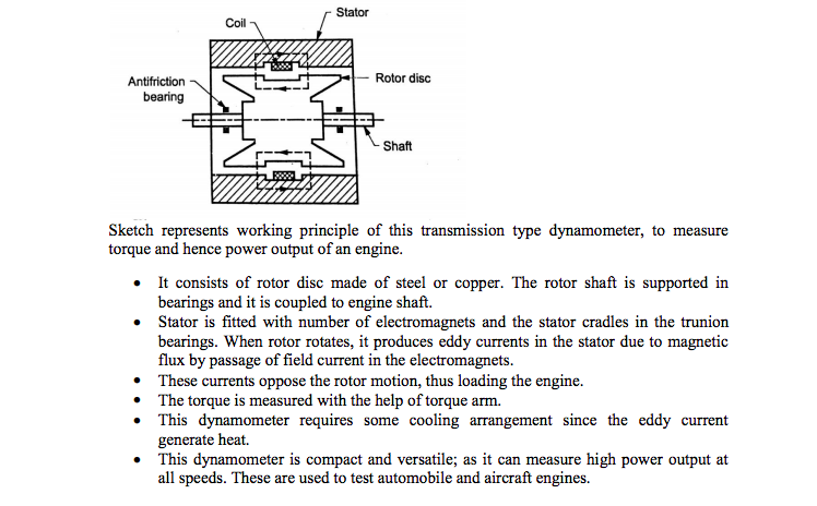
Explain construction and working of eddy current dynamometer. Answer:
 |
4 |
view | |||||||||||||||
| Q 4 e ) |
Question:
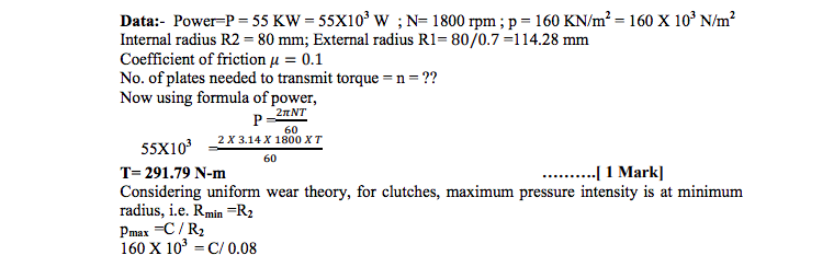
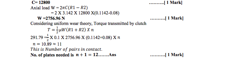
A multiplate disc clutch transmits 55 kW of power at 1800 rpm. Coefficient of friction for the friction surfaces is 0.1. Axial intensity of pressure is not to exceed 160 kN/m2 . The internal radius is 80 mm and is 0.7 times the external radius. Find the number of plates needed to transmit the required torque. Answer:
  |
4 |
view | |||||||||||||||
| Q 4 f ) |
Question:
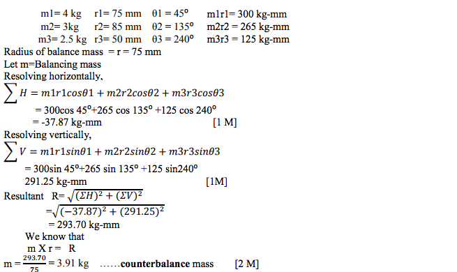
A rotor having the following properties : m1 = 4 kg r1 = 75 mm θ1 = 45o m2 = 3 kg r2 = 85 mm θ2 = 135o m3 = 2.5 kg r3 = 50 mm θ3 = 240o Determine the amount of the countermass at a radial distance of 75 mm required for the static balance. Answer:
|
4 |
view | |||||||||||||||
| Q 5 a ) |
Question:
Answer:
  |
8 |
view | |||||||||||||||
| Q 5 a ) |
Question:
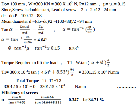
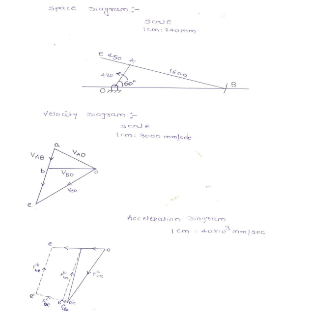
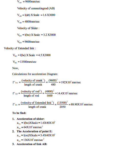
A screw jack is used to lift a load of 50 kN through a maximum lift of 200 mm. The material used for a screw is steel of allowable stresses in tension and compression as 100 N/mm2 and 50 N/mm2 respectively. The pitch of screw is 8 mm. The nut is made of phosphor bronze with allowable stresses as 50 N/mm2 and 45 N/mm2 in tension and crushing. The allowable shear stress for nut material is 40 N/mm2 . The allowable bearing pressure between nut and screw is not to exceed 20 N/mm2 . If the coefficient of friction between screw and nut is 0.14, design the screw and nut Answer:
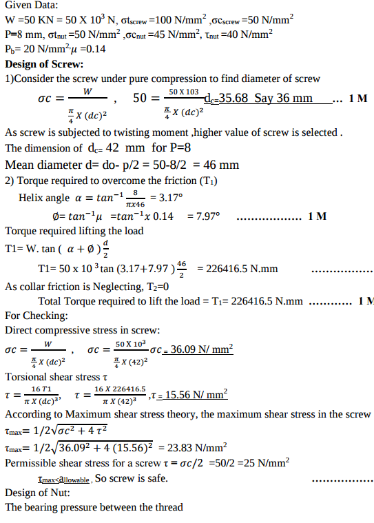 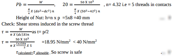 |
8 |
view | |||||||||||||||
| Q 5 a ) |
Question:
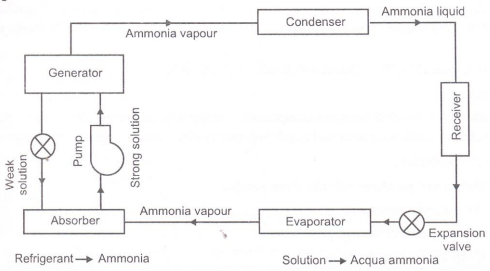
Explain with neat block diagram the working of ‘Vapour Absorbtion Cycle’. Answer:
|
8 |
view | |||||||||||||||
| Q 5 a ) |
Question:
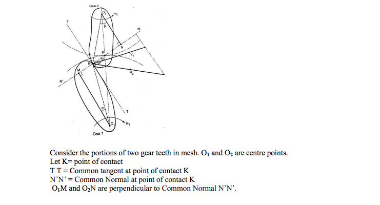
State and explain Law of Gearing. Answer:
|
4 |
view | |||||||||||||||
| Q 5 b ) |
Question:
Draw the profile of cam operating a roller reciprocating follower with the following data : Minimum radius of cam = 25 mm lift = 30 mm Roller diameter = 15 mm The cam lifts the follower for 120owith SHM followed by a dwell period of 30o. Then the follower lowers down during 150o of the cam rotation with uniform acceleration and deceleration followed by a dwell period. Answer:
  |
8 |
view | |||||||||||||||
| Q 5 b ) |
Question:
A railway wagon having 1500 kg mass and moving at 1 m/s velocity dashes against a bumper consisting of two helical springs of spring index 6. The springs, which get compressed by 150 mm while resisting a dash made of spring steel having allowable shear stress of 360 N/mm2 and modulus of rigidity 8.4 104 N/mm2 . Design the helical coil spring with circular crosssection of spring wire. Answer:
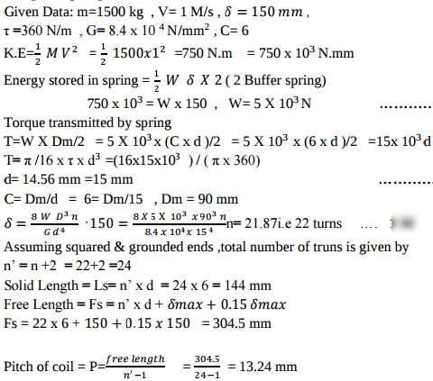 |
8 |
view | |||||||||||||||
| Q 5 b ) |
Question:
What do you mean by ‘Perfect Intercolling’ ? Explain with the help of P.V. diagram. Answer:
|
8 |
view | |||||||||||||||
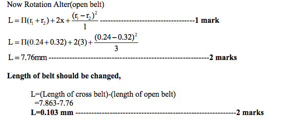
| Q 5 c ) |
Question:
Two parallel shafts, connected by a crossed belt, are provided with pulleys 480 mm and 640 mm in diameters. The distance between the centre lines of the shafts is 3 m. Find by how much the length of the belt should be changed if it is desired to alter the direction of rotation of the driven shaft. Answer:
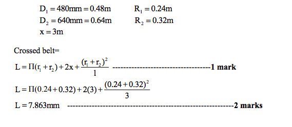  |
8 |
view | |||||||||||||||
| Q 5 c ) |
Question:
Explain the working of ‘Turbo-Prop’ engine with neat sketch. Answer:
|
8 |
view | |||||||||||||||
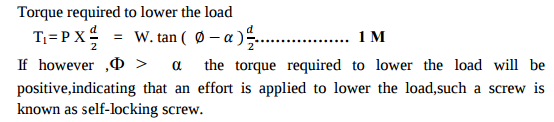
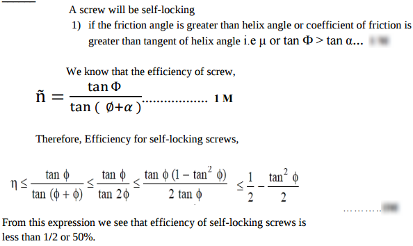
| Q 5c)(i) |
Question:
Show that the efficiency of self locking screw is less than 50% Answer:
  |
8 |
view | |||||||||||||||
| Q 5c)(ii) |
Question:
State any four advantages of ball bearings over plain journal bearings. Answer:
|
8 |
view | |||||||||||||||
| Q 6 ) |
Question:
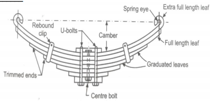
Draw a neat sketch of leaf spring of semi-elliptical type and name its parts. Answer:
|
4 |
view | |||||||||||||||
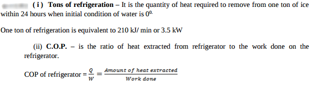
| Q 6 a ) |
Question:
State the following term : i) Tonnes of refrigeration ii) COP Answer:
 |
4 |
view | |||||||||||||||
| Q 6a)(i) |
Question:
Explain steep and creep phenomenon in belts. Answer:
|
4 |
view | |||||||||||||||
| Q 6a)(ii) |
Question:
Explain single cylinder 4-stroke I.C. engine using turning moment diagram. Answer:
|
4 |
view | |||||||||||||||
| Q 6 b ) |
Question:
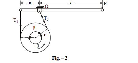
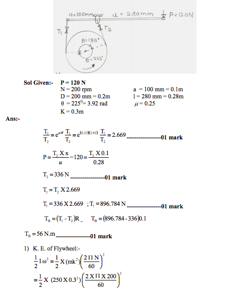
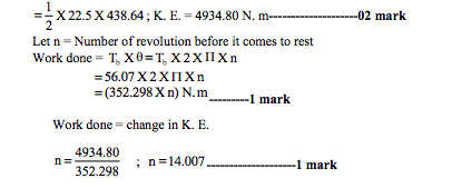
A simple band brake shown in figure 2 is applied to a shaft carrying a flywheel of mass 250 kg and of radius of gyration 300 mm. The shaft speed is 200 rpm. The drum diameter is 200 mm and the coefficient of friction is 0.25. The dimensions a and l are 100 mm and 280 mm respectively and the angle β = 135o. Determine (i) the brake torque when a force of 120 N is applied at the lever end. (ii) the number of turns of the flywheel before it comes to rest. (iii) the time taken by flywheel to come to rest.
Answer:
|
8 |
view | |||||||||||||||
| Q 6 b ) |
Question:
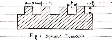
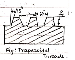
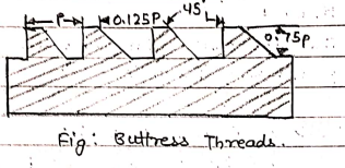
Explain different forms of threads with their relative advantages and applications. Answer:
|
|||||||||||||||||
|
Screw Form |
Characteristic |
Application |
||||||||||||||||
|
Sq. Thread
|
No side thrust Higher efficiency |
Used for general purpose power transmission |
||||||||||||||||
|
Trapezoidal Threads |
Stronger than square threads Easy to manufacture Wear compensation |
Used for higher power transmission |
||||||||||||||||
|
ACME threads |
Stronger than square threads Easy to manufacture Wear compensation |
Used for higher power transmission |
||||||||||||||||
|
Buttress threads |
Can bear very heavy load in one direction |
Used to handle heavy forces in one direction, like in truck jack |
4 |
view | ||||||||||||||
| Q 6 b ) |
Question:
Why majority of air compressors available in the market are multi staged ? Explain Answer:
|
4 |
view | |||||||||||||||
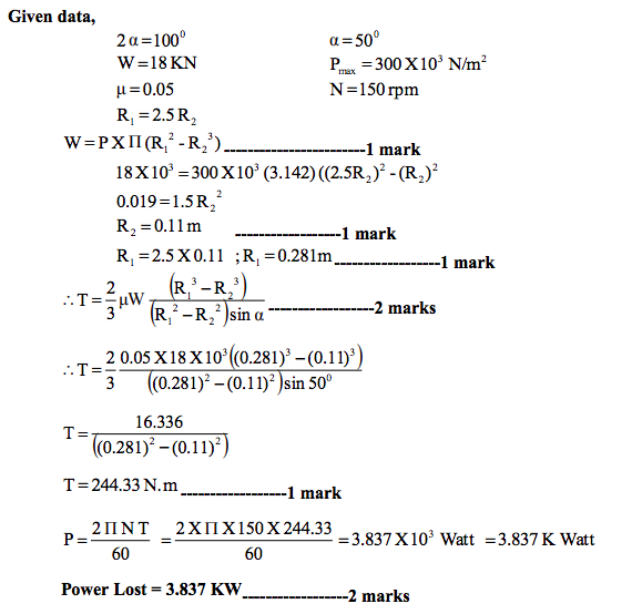
| Q 6 c ) |
Question:
A conical pivot with angle of cone as 100o, supports a load of 18 kN. The external radius is 2.5 times the internal radius. The shaft rotates at 150 rpm. If the intensity of pressure is to be 300 kN/m2 and coefficient of friction as 0.05, what is the power lost in working against the friction ? Answer:
 |
8 |
view | |||||||||||||||
| Q 6 c ) |
Question:
Determine the size of bolt in the cylinder head of a steam engine. The engine cylinder has a bore of 400 mm and the maximum steam pressure to which the cylinder is subjected is 1.5 N/mm2 . Cylinder head is held on the cylinder by 16 number of bolts. The permissible tensile stress for the bolt material is 25 N/mm2 Answer:
|
4 |
view | |||||||||||||||
| Q 6 c ) |
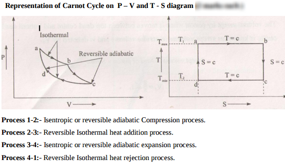
Question:
Represent Carnot cycle on P-V and T-S diagram Answer:
 |
4 |
view | |||||||||||||||
| Q 6 d ) |
Question:
State any four disadvantages of rolling bearings as compared to journal bearings Answer:
|
4 |
view | |||||||||||||||
| Q 6 d ) |
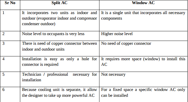
Question:
Compare between window air conditioner and split air conditioner (any four) Answer:
 |
4 |
view | |||||||||||||||
| Q 6 e ) |
Question:
Explain any one method to improve thermal efficiency of gas turbine with the help of block diagram. Answer:
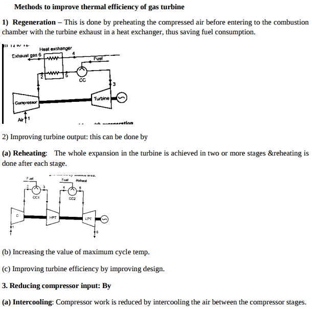 + + |
4 |
view |
| Que.No | Question/Problem | marks | Link |
|---|---|---|---|
| Q ) |
Question:
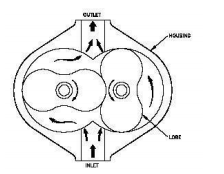
Explain with neat sketch working of lobe type air compressor. Answer:
|
4 |
view |
| Q 1a)(a) |
Question:
State four assumptions made for air standard cycle. Answer:
|
4 |
view |
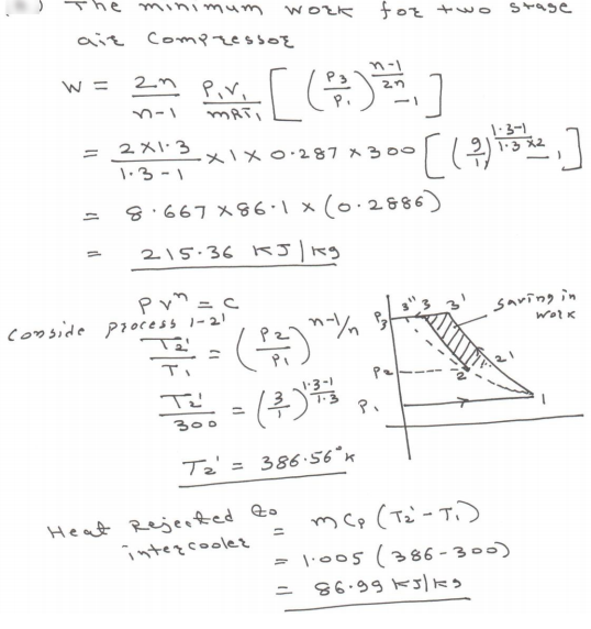
| Q 1a)(b) |
Question:
A two stage air compressor with perfect intercooling takes in air at 1 bar pressure and 27 °C. The law of compression in both the stages is Pv1.3 = constant. The compressed air is delivered at 9 bar from the H.P. Cylinder to an air receiver. Calculate per kg. of air i) The minimum work done. ii) The heat rejected to the intercooler. Answer:
 |
4 |
view |
| Q 1a)(c) |
Question:
Compare SI and CI engine on the basis of i) fuel used, ii) Compression ratio, iii) Weight, iv) Noise and vibration Answer:
|
4 |
view |
| Q 1a)(i) |
Question:
Write any four applications oil hydraulic systems Answer:
|
4 |
view |
| Q 1a)(i) |
Question:
Define Kinematic link with one example. Answer:
|
2 |
view |
| Q 1a)(i) |
Question:
What is stress concentration? State its significance in design of machine elements Answer:
|
4 |
view |
| Q 1a)(ii) |
Question:
What are the effects of contaminants in the oil? Answer:
|
4 |
view |
| Q 1a)(ii) |
Question:
Write the design procedure of knuckle joint. Answer:
|
4 |
view |
| Q 1a)(ii) |
Question:
Name different mechanisms generated from a single slider crank chain. Answer:
|
2 |
view |
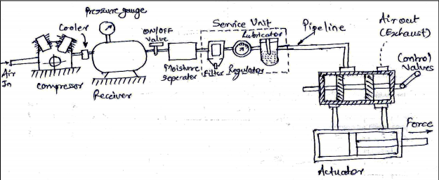
| Q 1a)(iii) |
Question:
Draw a general layout of pneumatic system and state the function of components Answer:
 |
4 |
view |
| Q 1a)(iii) |
Question:
Draw a neat sketch of flexible flange coupling and label its main components. Answer:
 |
4 |
view |
| Q 1a)(iii) |
Question:
State the advantages of roller follower over knife edge follower. Answer:
|
2 |
view |
| Q 1a)(iv) |
Question:
Draw the hydraulic circuit showing control of DA cylinder. Using 4 × 2 DC valve. Explain the working in brief. Answer:
|
4 |
view |
| Q 1a)(iv) |
Question:
Draw neat labeled sketches of Acme and square thread profile and state its relative characteristics. Answer:
 |
4 |
view |
| Q 1a)(iv) |
Question:
Define slip and creep in case of belt drive. Answer:
|
2 |
view |
| Q 1a)(v) |
Question:
Give four advantages of chain drive over belt drive. Answer:
|
2 |
view |
| Q 1a)(vi) |
Question:
State the effect of centrifugal tension on power transmission. Answer:
|
2 |
view |
| Q 1a)(vii) |
Question:
Define fluctuation of energy and coefficient of fluctuation of energy. Answer:
|
2 |
view |
| Q 1a)(viii) |
Question:
State the adverse effect of imbalance of rotating elements of machine. Answer:
|
2 |
view |
| Q 1b)(a) |
Question:
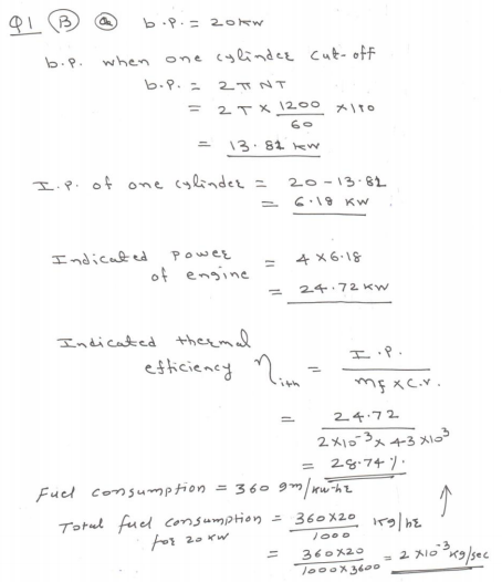
A four cylinder engine running at 1200 rpm delivers 20 kW. The average torque when one cylinder was cut is 110 N.m. Find the indicated thermal efficiency if the calorific value of the fuel is 43 MJ/Kg and the engine uses 360 gm. of gasoline (fuel) per kW. hr. Answer:
 |
6 |
view |
| Q 1b)(b) |
Question:
Explain with neat sketch working of non dispersive infra red (NDIR) gas analyser. Answer:
|
6 |
view |
| Q 1b)(i) |
Question:
State any four inversions of single slider crane chain. Describe any one with neat sketch. Answer:
|
4 |
view |
| Q 1b)(i) |
Question:
Draw actual hydraulic system and explain its working. Answer:
|
6 |
view |
| Q 1b)(i) |
Question:
State and explain main considerations in machine design. Answer:
|
6 |
view |
| Q 1b)(ii) |
Question:
Compare multiplate clutch with cone clutch on the following basis. (1) Power Transmission (2) Size Answer:
|
4 |
view |
| Q 1b)(ii) |
Question:
Explain with neat sketch the working of rotary spool type DC valve. Answer:
|
6 |
view |
| Q 1b)(ii) |
Question:
A hollow shaft is required to transmit 50 kW power at 600 rpm. Calculate its inside and outside diameters if its ratio is 0.8. Consider yield strength of material as 380N/mm2 and factor of safety as 4. Answer:
|
6 |
view |
| Q 1b)(iii) |
Question:
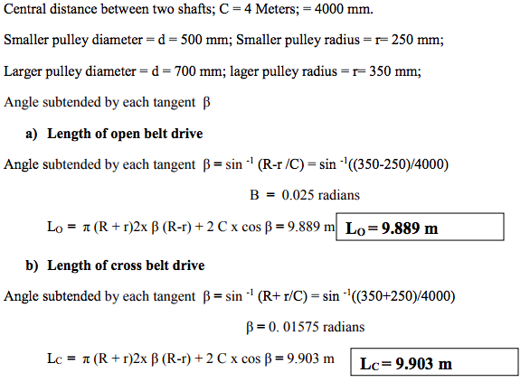
The central distance two shaft is 4m having two pulleys with diameter having 500mm and 700mm respectively find the length of belt required - (1) for open belt drive (2) for cross belt drive Answer:
 |
4 |
view |
| Q 2 a ) |
Question:
Explain with the help of neat sketches three basic types of lever. State one application of each type. Answer:
|
8 |
view |
| Q 2 a ) |
Question:
Explain a scotch yoke mechanism with a neat sketch. Answer:
 |
4 |
view |
| Q 2 a ) |
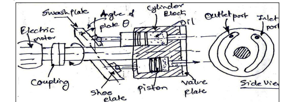
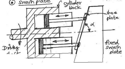
Question:
What is swash plate? What is its use? What will happen if we change the angle of swash plate? Explain with sketch Answer:
|
8 |
view |
| Q 2 a ) |
Question:
Differentiate vapour compression and vapour absorption refrigeration system. (min. eight points of difference) Answer:
|
8 |
view |
| Q 2 a ) |
Question:
Why pressure relief valve is used in hydraulic circuit? Explain in details with neat sketches Answer:
|
8 |
view |
| Q 2 b ) |
Question:
Explain with the help of neat sketches, the design procedure of a square sunk key Answer:
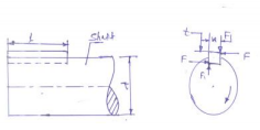 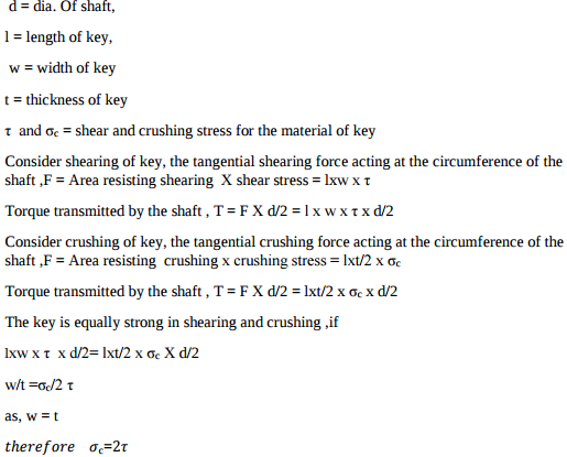 |
8 |
view |
| Q 2 b ) |
Question:
What is machine ? Differentiate between a machine and a structure. Answer:
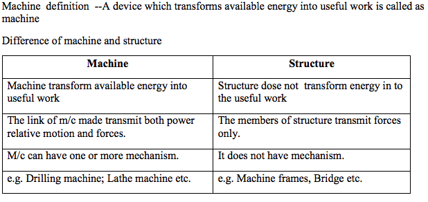 |
4 |
view |
| Q 2 b ) |
Question:
A single stage reciprocating air compressor has a swept volume of 2000 cm3 and runs at 800 rpm. It operates on a pressure ratio of 8 with a clearance 5% of the swept volume. Assume NTP room conditions at inlet (p = 101.3 kPa t = 15°C) and polytropic compression and expansion with n = 1.25 calculate i) Indicated power, ii) Volumetric efficiency, iii) Mass flow rate iv) Isothermal efficiency Answer:
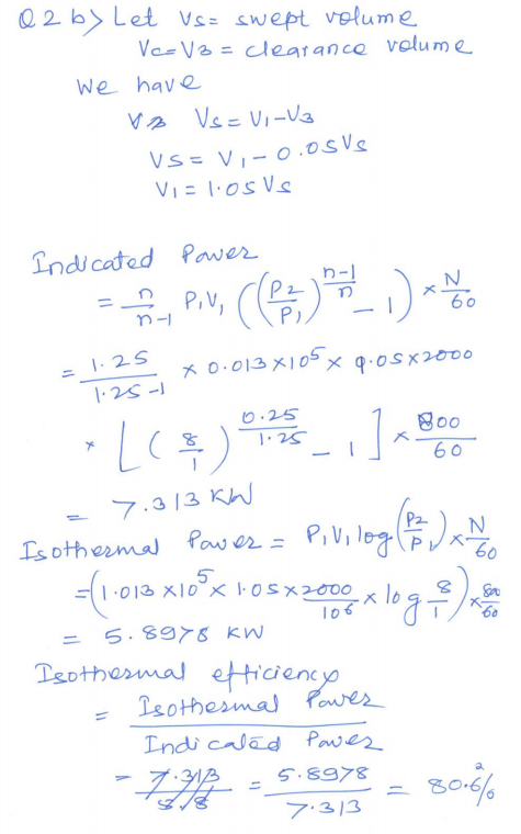 |
8 |
view |
| Q 2 c ) |
Question:
Explain Klein’s construction to determine velocity and acceleration of different links in single slider crank mechanism. Answer:
|
4 |
view |
| Q 2 c ) |
Question:
Explain the construction and working of doubled acting reciprocating compressor with neat sketch. Answer:
|
8 |
view |
| Q 2 c ) |
Question:
A four stroke gas engine has a cylinder diameter of 25 cm and stroke 45 cm. The effective diameter of brake is 1.6 m. The observations made in a test of the engine were as follows. Duration of test = 40 min. Total no. of revolutions = 8080 Total no. of explosions = 3230 Net load on brake = 90 kg Mean effective pressure = 5.8 bar Volume of gas used = 7.5 m3 Pressure of gas = 136 mm of water Atm. temp. = 17°C Calorific value of gas = 19 MJ/m3 at NTP Rise in temp. of jacket cooling water = 45°C Cooling water supplied = 180 kg Draw heat balance sheet and estimate indicated thermal efficiency and brake thermal efficiency. Assume atmospheric pr. as 760 mm of Hg. Answer:
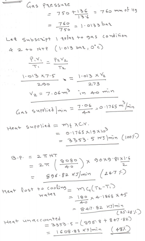 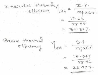 |
8 |
view |
| Q 2c)(i) |
Question:
State applications of maximum shear stress theory and principal normal stress theory Answer:
|
8 |
view |
| Q 2c)(ii) |
Question:
State two applications each of cotter joint and knuckle joint. Answer:
|
8 |
view |
| Q 2 d ) |
Question:
Define the terms: (i) Linear velocity (ii) Angular velocity (iii) Absolute velocity (iv) Relative velocity Answer:
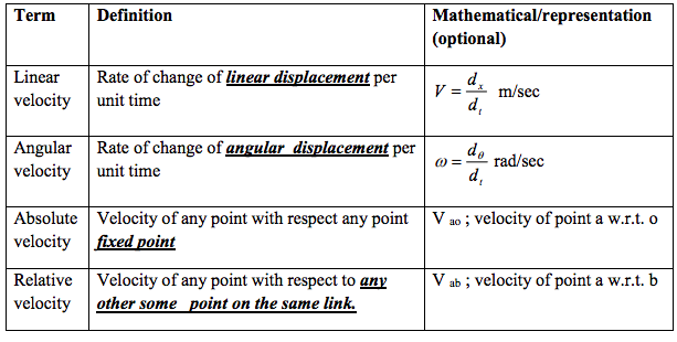 |
4 |
view |
| Q 2 d ) |
Question:
Explain with neat sketch different types of follower. Answer:
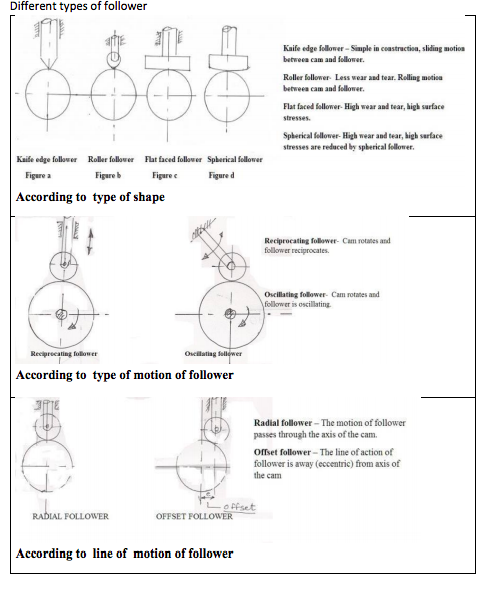 |
4 |
view |
| Q 2 f ) |
Question:
A pulley is driven by the flat belt running at speed of 600m/min. and transmit 4 kW. The coefficient of friction between belt and pulley is 0.3 and angle of lap is 160°. Find maximum tension in the belt. Answer:
|
4 |
view |
| Q 3 a ) |
Question:
Discuss the following motion of the follower by drawing the displacement velocity and acceleration diagram. (i) Uniform Velocity (ii) Simple Harmonic Motion (iii) Uniform acceleration and retardation Answer:
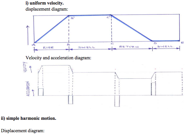 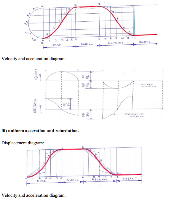 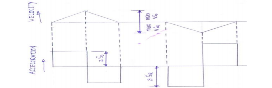 |
4 |
view |
| Q 3 a ) |
Question:
State the composition of the materials 30 Ni 16 Cr5, 40C8, FeE230 X15Cr25Ni 12 Answer:
|
4 |
view |
| Q 3 a ) |
Question:
Write any four advantages of oil hydraulic system. Answer:
|
4 |
view |
| Q 3 a ) |
Question:
List any four pollutants in exhaust gases of I.C. engine with their effects. Answer:
|
4 |
view |
| Q 3 b ) |
Question:
The crank and connecting rod of steam engine are 0.5m and 2m long respectively. The crank makes 180r.p.m. in clockwise direction. When it has turned through 45° from I.D.C. Find the velocity of piston and angular velocity of connecting rod by relative velocity method. Answer:
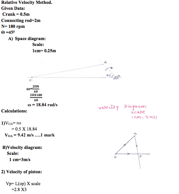 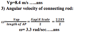 |
4 |
view |
| Q 3 b ) |
Question:
Design single cotter joint to transmit 200 kN. Allowable stresses for the material are 75 MPa in tension and 50 MPa in shear. Answer:
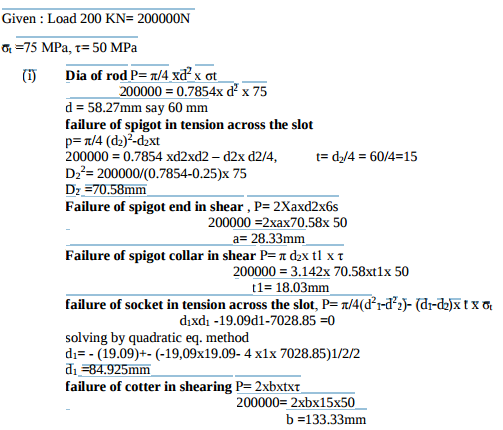 |
4 |
view |
| Q 3 b ) |
Question:
Draw symbols of: (i) Oil reservoir (ii) Oil filter (iii) Heat exchanger (iv) Unidirectional fixed displacement pump. Answer:
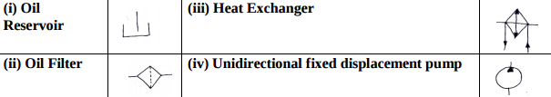 |
4 |
view |
| Q 3 b ) |
Question:
Compare closed cycle and open cycle gas turbine. Answer:
|
4 |
view |
| Q 3 c ) |
Question:
Compare cross belt drive and open belt drive on the basis of - (i) Velocity ratio (ii) Direction of driven pulley (iii) Application (iv) Length of belt drive Answer:
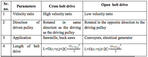 |
4 |
view |
| Q 3 c ) |
Question:
State the ‘Lewis equation’ for spur gear design. State SI unit of each term in the equation. Answer:
|
4 |
view |
| Q 3 c ) |
Question:
Explain the principle of regenerative circuit. Answer:
|
4 |
view |
| Q 3 c ) |
Question:
Define i) Humidity ratio, ii) Specific humidity Answer:
|
4 |
view |
| Q 3 d ) |
Question:
State the applications of : (i) Band brake (ii) Disc brake (iii) Internal expanding shoe brake (iv) External shoe brake Answer:
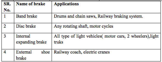 |
4 |
view |
| Q 3 d ) |
Question:
Explain why bolts of uniform strength are preferred. Draw sketches of two different types of bolts of uniform strength Answer:
|
4 |
view |
| Q 3 d ) |
Question:
Three masses 10 kg, 20 kg and 15kg are attached at a point at radii of 20 cm, 25cm and 15 cm respectively. If the angle between successive masses is 60° and 90°. Determine analytically the balancing mass to be attached at radius of 30cm. Answer: |
4 |
view |
| Q 3 d ) |
Question:
What is FRL unit? Explain its function Answer:
|
4 |
view |
| Q 3 d ) |
Question:
Name four sensors used in I.C. engine and explain working of any one. Answer:
|
4 |
view |
| Q 3 e ) |
Question:
What is scavenging in I.C. engine ? State its types. Answer:
|
4 |
view |
| Q 3 e ) |
Question:
Prove that for a square key sc = 2t where sc = crushing stress t = shear stress. Answer:
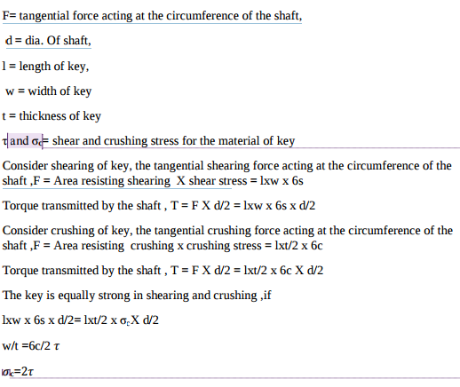 |
4 |
view |
| Q 3 e ) |
Question:
Draw pilot operated DA cylinder circuit using 4 × 2 DC valve and 3 × 2 pilot valve Answer:
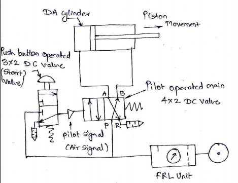 |
4 |
view |
| Q 3 f ) |
Question:
Explain with neat sketch working principle of epicyclic gear train. Answer:
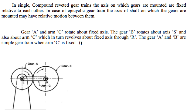 |
4 |
view |
| Q 4 a ) |
Question:
Generally, the lower side is kept “Tight side” and upper side is kept as “Slack side” with the belt drives having small driving pulley and big driven pulley. Why ? Answer:
|
4 |
view |
| Q 4a)(a) |
Question:
Explain the process of combustion in diesel engine. Answer:
|
4 |
view |
| Q 4a)(b) |
Question:
Explain battery ignition in S.I. engine. Answer:
|
4 |
view |
| Q 4a)(c) |
Question:
State the norms of Bharat stage III and IV Answer:
|
4 |
view |
| Q 4a)(d) |
Question:
State different methods for improving thermal efficiency of gas turbine and explain any one. Answer:
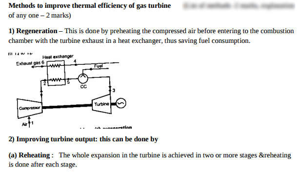 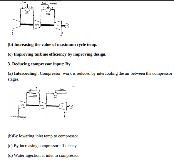 |
4 |
view |
| Q 4a)(i) |
Question:
What is the use of direction control valve? Explain with sketch. Answer:
|
4 |
view |
| Q 4a)(i) |
Question:
State four examples of ergonomic considerations in the design of a lathe machine. Answer:
|
4 |
view |
| Q 4a)(ii) |
Question:
Draw bleed off circuit and label it Answer:
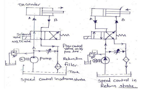 |
4 |
view |
| Q 4a)(ii) |
Question:
Write the equation with Wahl’s factor, used for design of helical coil spring. State the SI unit of each term in the equation Answer:
 |
4 |
view |
| Q 4a)(iii) |
Question:
What are the limitations of pneumatic system? Answer:
|
4 |
view |
| Q 4a)(iii) |
Question:
State four important modes of gear failure. Answer:
|
4 |
view |
| Q 4a)(iv) |
Question:
Draw symbol of: 1) 2 × 2 DC valve 2) Fixed type flow control valve 3) Pressured relief valve. 4) Muffler Answer:
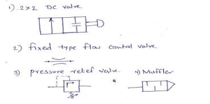 |
4 |
view |
| Q 4a)(iv) |
Question:
State four disadvantages of screwed joints. Answer:
|
4 |
view |
| Q 4 b ) |
Question:
Describe with neat sketch the working of Oldham’s coupling. Answer:
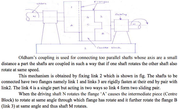 |
4 |
view |
| Q 4b)(a) |
Question:
Define – (i) Indicated power, (ii) Mechanical efficiency, (iii) BSFC Answer:
|
6 |
view |
| Q 4b)(b) |
Question:
List the additives of lubricant used in S.I engine and state their advantages. Answer:
|
6 |
view |
| Q 4b)(i) |
Question:
What is the meaning of unidirectional air motor and bi directional air motor? Explain with sketch and draw symbol of both Answer:
|
6 |
view |
| Q 4b)(i) |
Question:
Explain the design procedure of shaft on the basis of torsional rigidity. State the equation with SI units. State two applications of this approach. Answer:
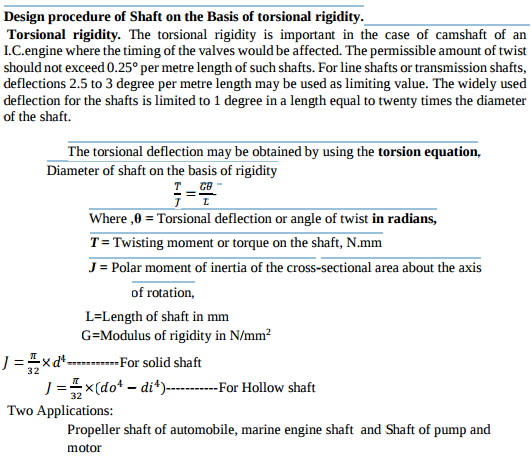 |
6 |
view |
| Q 4b)(ii) |
Question:
Compare linear actuators and rotary actuators. Answer:
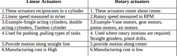 |
6 |
view |
| Q 4b)(ii) |
Question:
Draw S-N curve. Explain the concept of endurance limit and its need in design of machine elements Answer:
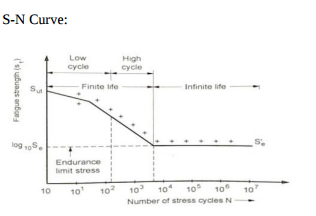 |
6 |
view |
| Q 4 c ) |
Question:
Distinguish between flywheel and governor. Answer:
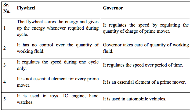 |
4 |
view |
| Q 4 d ) |
Question:
Discuss the working of Rope brake dynamometer with the help of a neat sketch. Answer:
 |
4 |
view |
| Q 4 e ) |
Question:
Explain the working of internal expanding shoe brake with the help of neat sketch. Answer:
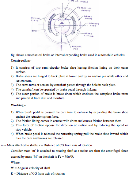 |
4 |
view |
| Q 4 f ) |
Question:
Explain the process of balancing of single rotating mass by a single mass rotating in the same plane. Answer:
|
4 |
view |
| Q 5 a ) |
Question:
A power screw on a machine has single start square thread with a non rotating bronze nut. Axial force on the screw is 15 kN. Allowable stresses for screw material in compression and shear are 85 MPa and 37 MPa respectively. Allowable bearing pressure for the screw nut pair is 5 MPa. Find (i) Core diameter of screw (ii) Length of the nut (iii) Efficiency of power screw in coefficient of friction between screw and nut is 0.12. (iv) Shear stresses in the threads of screw and nut. Answer:
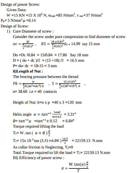 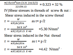 |
8 |
view |
| Q 5 a ) |
Question:
In a slider crank mechanism the length of crank and connecting rod are 100mm and 40mm respectively. The crank rotates uniformly at 600 rpm clockwise. Then crank has turned through 45° from I.D.C. Find by analytical method. (i) Velocity and acceleration of slider (ii) Angular velocity and angular acceleration of connecting rod. Answer:
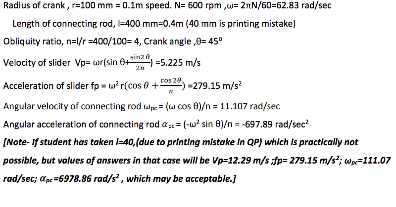 |
8 |
view |
| Q 5 a ) |
Question:
Explain with neat sketch construction and working of ice plant. Answer:
|
8 |
view |
| Q 5a)(i) |
Question:
Draw symbol of any three types of Hydraulic motors. Answer:
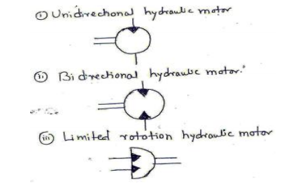 |
8 |
view |
| Q 5a)(ii) |
Question:
What is impulse circuit? Explain Answer:
|
8 |
view |
| Q 5 b ) |
Question:
Design a helical compression spring with ground ends. The spring index is 12. Maximum load on the spring is 100N and deflection under maximum load is 15 mm. Allowable shear stress of the material is 100 MPa and modulus of rigidity is 4 MPa. Find wire and spring diameters, number of coils and stiffness of spring. Answer:
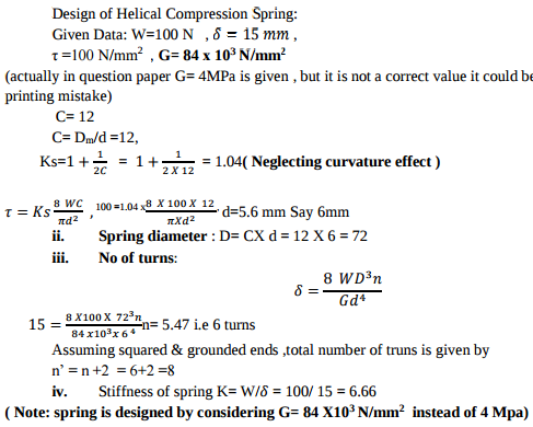 |
8 |
view |
| Q 5 b ) |
Question:
Draw profile of cam to raise the valve with S.H.M. through 5cm in 120° of revolution, keep it fully raised through 30° and lower it with equal uniform acceleration and retardation through 90° of rotation. The valve remain closed during the rest of rotation. The diameter of the roller is 2 cm and the minimum radius of the cam is 5cm. The axis of the valve rod is offset 2cm from the axis of the shaft. Assume the cam rotating in clockwise direction. Answer:
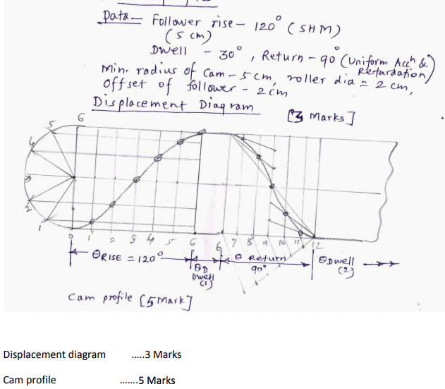 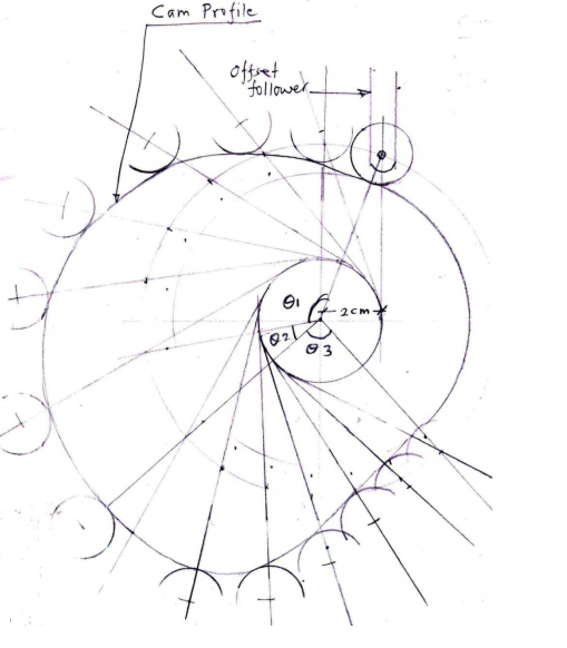 |
8 |
view |
| Q 5 b ) |
Question:
Explain construction and working of gear pump. Answer:
|
8 |
view |
| Q 5 b ) |
Question:
A single cylinder reciprocating compressor has a bore of 120 mm and a stroke of 150 mm. and is driven at a speed of 1200 rpm. It is compressing CO2 gas from a pressure of 120 Kpa and temp. of 20°C to a temp. of 215°C. Assuming polytropic compression with n = 1.3, no clearance and volumetric efficiency of 100% calculate (i) pressure ratio, (ii) Indicated power, (iii) shaft power with mech. efficiency 80%, (iv) mass flow rate Answer:
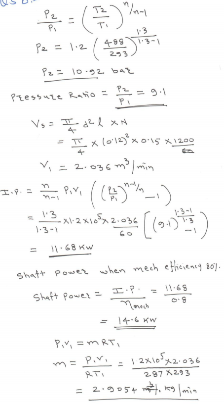 |
8 |
view |
| Q 5 c ) |
Question:
Answer:
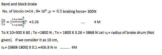 |
8 |
view |
| Q 5 c ) |
Question:
Explain working of directly operated (Poppet type) check valve with neat sketch. Answer:
|
8 |
view |
| Q 5 c ) |
Question:
Explain with neat sketch construction and working of constant volume gas turbine. Answer:
|
8 |
view |
| Q 5c)(i) |
Question:
State the steps involved in selection of a proper ball bearing from a manufacturer’s catalogue. Answer:
|
8 |
view |
| Q 5c)(ii) |
Question:
State two engineering applications of each of Acme and Buttress thread profiles with neat sketches. Answer:
|
8 |
view |
| Q 6 a ) |
Question:
Derive strength equation for parallel fillet weld subjected to tensile load. Answer:
|
4 |
view |
| Q 6 a ) |
Question:
In cold climate why oil tank is equipped with oil heaters? Explain. Answer:
|
4 |
view |
| Q 6 a ) |
Question:
What is the necessity of purification of air in compressor and how it is done ? Answer:
|
4 |
view |
| Q 6a)(i) |
Question:
Define the following terms as applied to cam with neat sketch. (1) Pitch circle (2) Pressure angle (3) Stroke of follower (4) Module Answer:
|
4 |
view |
| Q 6a)(ii) |
Question:
Differentiate between disc brake and internally expanding brake. Answer:
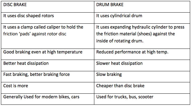 |
4 |
view |
| Q 6 b ) |
Question:
PQRS is a four bar chain with link PS fixed. The lengths of links are PQ = 62.5mm, QR = 175mm, RS = 112.5mm and PS = 200mm, The crank PQ rotates at 10 rad/sec clockwise. Draw velocity and acceleration diagram, when angle QPS = 60° and Q and R lie on the same side of PS. Find the angular velocity and angular acceleration of links QR and RS. Answer:
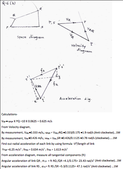 |
8 |
view |
| Q 6 b ) |
Question:
State two applications of leaf spring. Draw neat sketch of leaf spring Answer:
|
4 |
view |
| Q 6 b ) |
Question:
Compare meter in circuit and meter out circuit Answer:
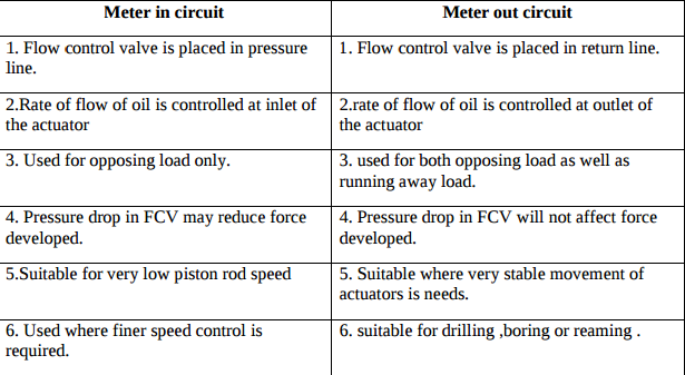 |
4 |
view |
| Q 6 b ) |
Question:
A diesel engine has a compression ratio of 14 and cut-off takes place at 6% of stroke. Find the air standard efficiency. Answer:
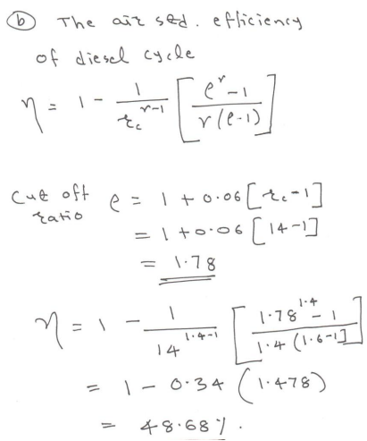 |
4 |
view |
| Q 6 c ) |
Question:
Determine the power lost in a footstep bearing due to friction if a load of 15 kN is supported and the shaft is rotating at 100 r.p.m. The diameter of bearing is 15cm and coefficient of friction is 0.05. Assume : (i) Uniform wear condition (ii) Uniform pressure condition. Answer:
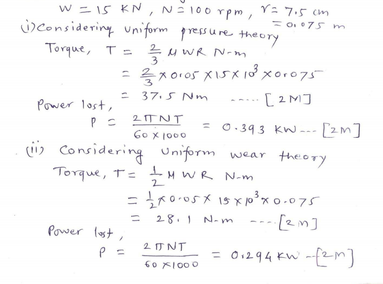 |
8 |
view |
| Q 6 c ) |
Question:
A steam engine cylinder has effective diameter of 250 mm. It is subjected to maximum steam pressure of 1.5 MPa. The cylinder cover is fixed to the cylinder with the help of 12 bolts. The pitch circle diameter of bolts is 400 mm. Permissible tensile stress of the bolt material is 30 MPa. Determine nominal diameter of the bolts. Answer:
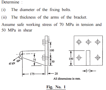 |
4 |
view |
| Q 6 c ) |
Question:
Draw the hydraulic circuit for shaping machine. Explain its working Answer:
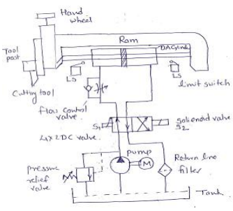 |
4 |
view |
| Q 6 c ) |
Question:
Define (i) Dew point temp. (ii) Wet bulb temp Answer:
|
4 |
view |
| Q 6 d ) |
Question:
Differentiate between sliding contact and rolling contact type bearings. Answer:
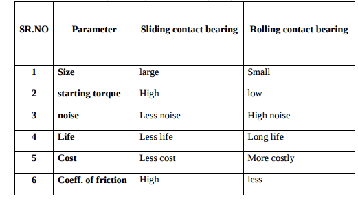 |
4 |
view |
| Q 6 d ) |
Question:
Draw constructional details of pneumatic hose. Why hose is required in pneumatic circuits? Answer:
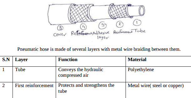 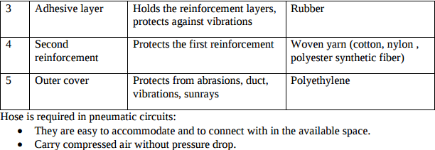 |
4 |
view |
| Q 6 d ) |
Question:
Explain the principle of Ram jet with neat sketch Answer:
|
4 |
view |
| Q 6 e ) |
Question:
State one application each of (i) Deep groove ball bearing (ii) Taper roller bearing (iii) Thrust roller bearing (iv) Needle roller bearing Answer:
|
4 |
view |
| Q 6 e ) |
Question:
A taper roller bearing has a dynamic load capacity of 26 kN. The desired life for 90% of the bearing is 8000 hr. and speed is 300 rpm. Calculate equivalent radial load that the bearing can carry Answer:
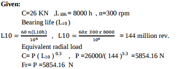 |
4 |
view |
| Q 6 e ) |
Question:
How can the speed control of any actuator be achieved? Explain the speed control circuit of bi directional air motor with sketch. Answer:
|
4 |
view |
| Q 6 e ) |
Question:
Draw neat sketch of split air conditioner and name the parts. Answer:
|
4 |
view |
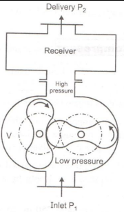
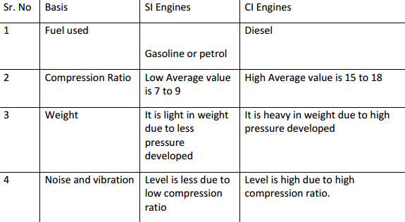
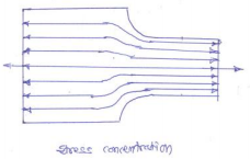
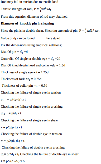
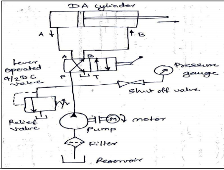
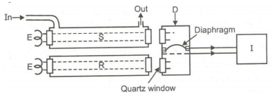
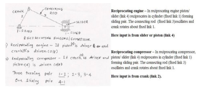
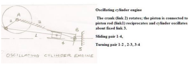
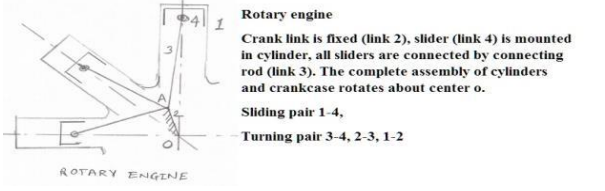
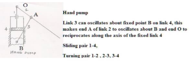
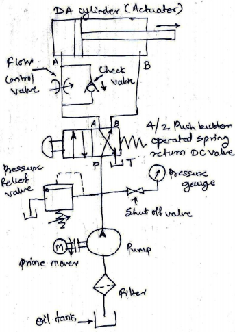
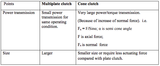
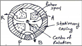
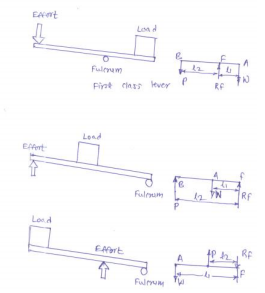
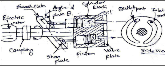
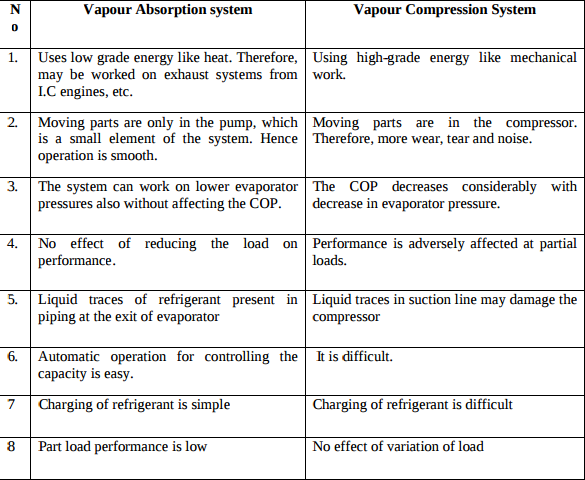
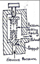
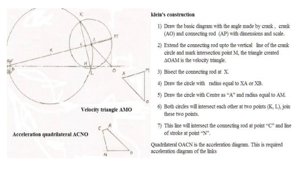
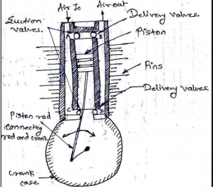
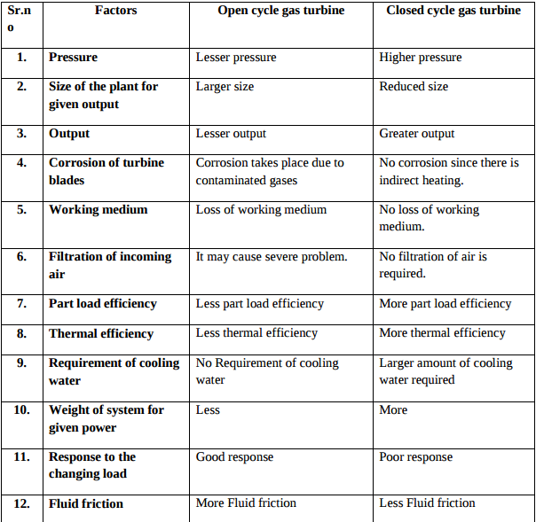
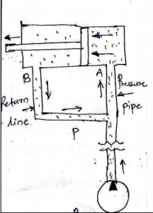
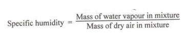
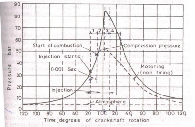
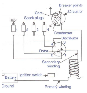
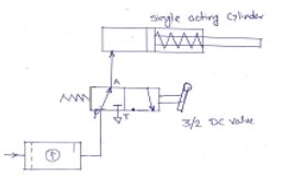
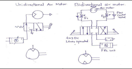
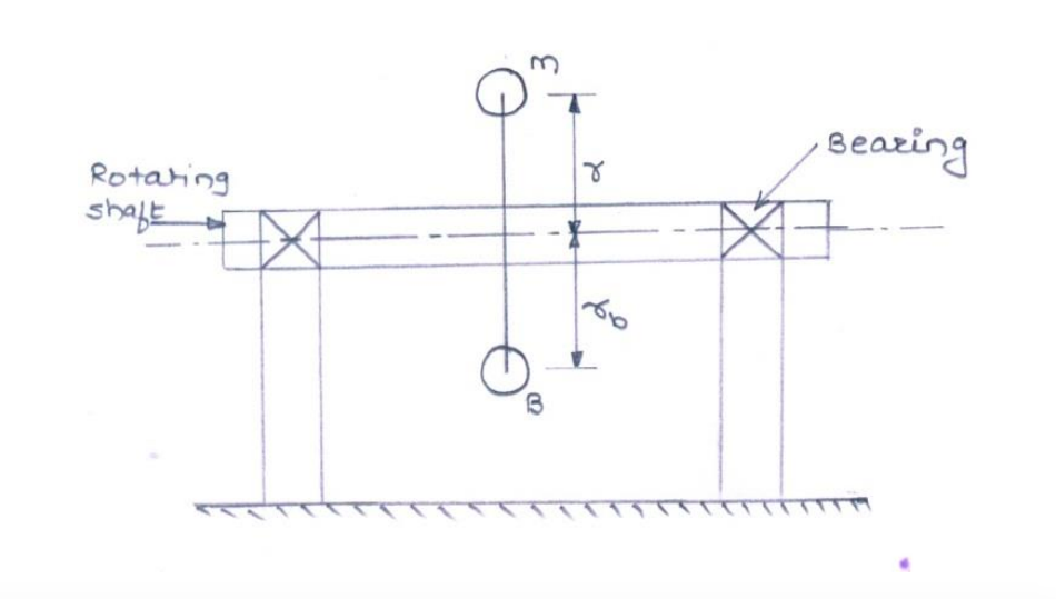
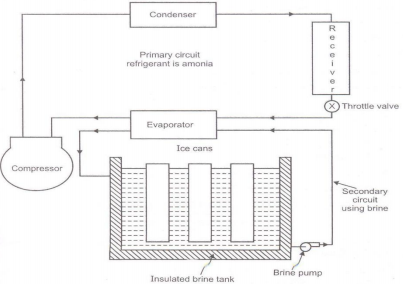
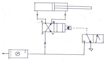
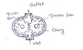
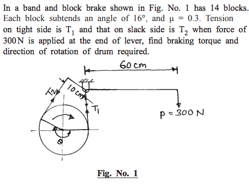
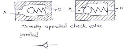
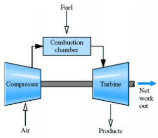
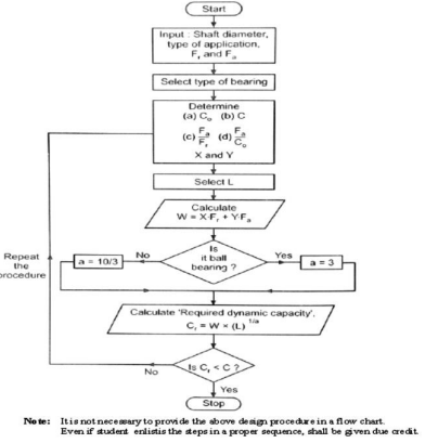
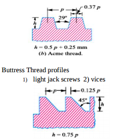
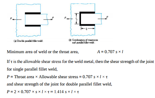
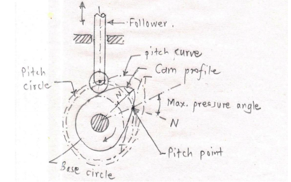
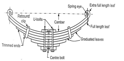
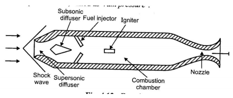
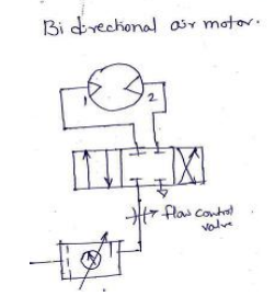
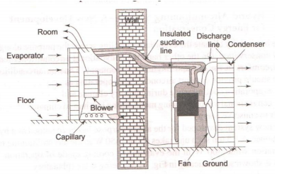
| Que.No | Question/Problem | marks | Link | ||||||||||||
|---|---|---|---|---|---|---|---|---|---|---|---|---|---|---|---|
| Q 1a)(a) |
Question:
Define kinematic link and kinematic chain. Answer:
|
2 |
view | ||||||||||||
| Q 1a)(a) |
Question:
Write the equations for air standard efficiency of otto cycle and diesel cycle and state various terms involved in it. Answer:
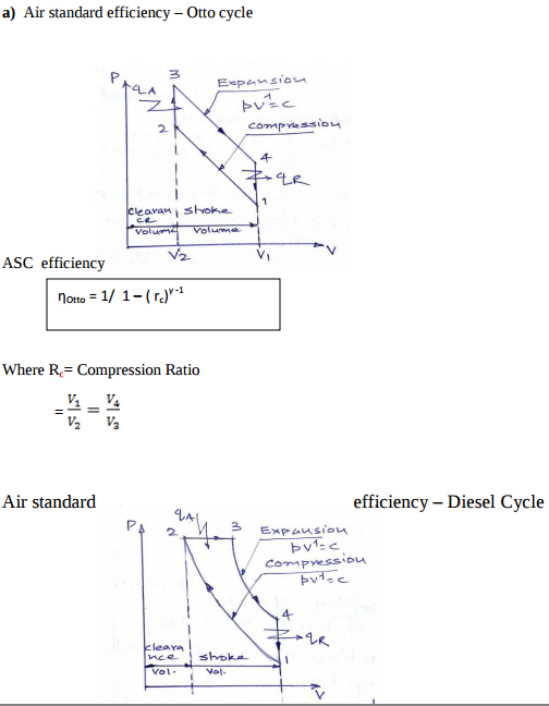 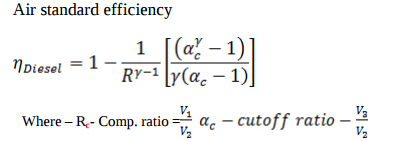 |
4 |
view | ||||||||||||
| Q 1a)(b) |
Question:
Enlist the different type of follower motion. Answer:
|
2 |
view | ||||||||||||
| Q 1a)(b) |
Question:
Define : i) Compression ratio (Rc) ii) Swept volume (vs) iii) Cut off ratio iv) Clearance volume (vc) Answer:
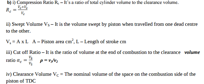 |
4 |
view | ||||||||||||
| Q 1a)(c) |
Question:
Define angle of lap and slip in belt drive. Answer:
|
2 |
view | ||||||||||||
| Q 1a)(c) |
Question:
Write uses of compressed air. Answer:
|
4 |
view | ||||||||||||
| Q 1a)(d) |
Question:
Draw a neat sketch of vane compressor and label the different parts. Answer:
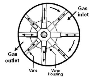 |
4 |
view | ||||||||||||
| Q 1a)(d) |
Question:
State four conditions under which the ‘V’ belt drive is selected. Answer:
|
2 |
view | ||||||||||||
| Q 1a)(e) |
Question:
State the function of Governor in an I.C. engine. Answer:
|
2 |
view | ||||||||||||
| Q 1a)(f) |
Question:
State four applications of flywheel. Answer:
|
2 |
view | ||||||||||||
| Q 1a)(g) |
Question:
Give the classification of dynamometer. State the function of it. Answer:
|
2 |
view | ||||||||||||
| Q 1a)(h) |
Question:
Why is balancing of rotating parts necessary for high speed engines ? Answer:
|
2 |
view | ||||||||||||
| Q 1b)(a) |
Question:
What is the necessity of I.C. Engine Testing ? What are the different test carried out on I.C. Engines ? Answer:
|
6 |
view | ||||||||||||
| Q 1b)(a) |
Question:
Define completely constrained motion and successfully constrained motion with neat sketch. State one example of each. Answer:
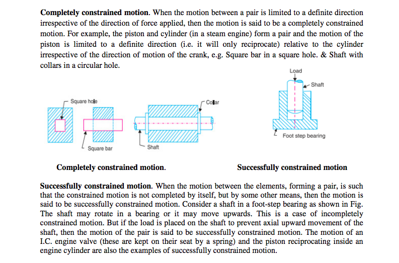 |
4 |
view | ||||||||||||
| Q 1b)(b) |
Question:
Explain the procedure for conducting Morse test. Answer:
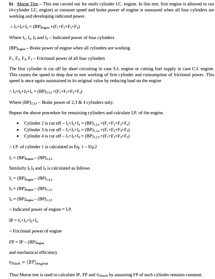 |
6 |
view | ||||||||||||
| Q 1b)(b) |
Question:
Explain working principle of clutch. State its location in transmission system of an automobile. Answer:
|
4 |
view | ||||||||||||
| Q 1b)(c) |
Question:
Compare cross belt drive and open belt drive on the basis of (i) velocity ratio (ii) application (iii) direction of driven pulley (iv) length of belt drive Answer:
|
4 |
view | ||||||||||||
| Q 2 a ) |
Question:
An I.C. Engine uses 6 kg of fuel having calorific value 44000 kJ/kg in one hour. The IP developed is 18 kW. The temperature of 11.5 kg of cooling water was found to rise through 25°C per minute. The temperature of 42 kg of exhaust gas with specific heat 1 kJ/kg°k was found to rise through 220°C. Draw the heat balance sheet for the engine. Answer:
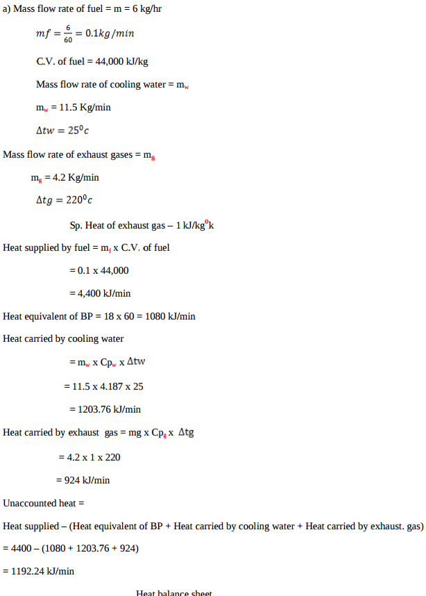 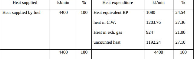 |
8 |
view | ||||||||||||
| Q 2 a ) |
Question:
Differentiate machine and structure on any four points. Answer:
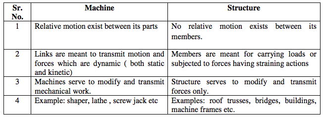 |
4 |
view | ||||||||||||
| Q 2 b ) |
Question:
What is the necessity of multistage compression ? Explain the working of two stage reciprocating air compressor with intercooler, with the help of p-v diagram. Answer:
|
8 |
view | ||||||||||||
| Q 2 b ) |
Question:
Explain with neat sketch working principle of Oldham’s coupling. Answer:
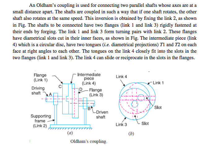 |
4 |
view | ||||||||||||
| Q 2 c ) |
Question:
Explain vapour compression refrigeration (for dry saturated state of refrigerant) cycle with the help of P-h and T-s charts. Answer:
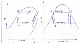  |
8 |
view | ||||||||||||
| Q 2 c ) |
Question:
Define linear velocity, angular velocity, absolute velocity and state the relation between linear velocity and angular velocity. Answer:
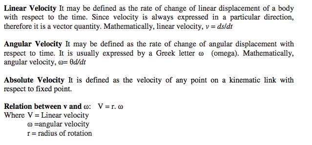 |
4 |
view | ||||||||||||
| Q 2 d ) |
Question:
Describe stepwise procedure for determination of velocity and acceleration by Klein’s construction with suitable data. Answer:
|
4 |
view | ||||||||||||
| Q 2 e ) |
Question:
Draw a neat sketch of radial cam with roller follower and show the following on it : (i) Pitch point (ii) Pressure angle (iii) Prime circle (iv) Trace point Answer:
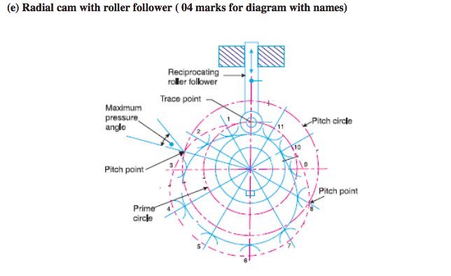 |
4 |
view | ||||||||||||
| Q 2 f ) |
Question:
The central distance between two shaft is 4 m having two pulleys with diameter having 500 mm and 700 mm respectively. Find length of belt required (i) for open belt drive (ii) for cross belt drive Answer:
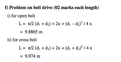 |
4 |
view | ||||||||||||
| Q 3 a ) |
Question:
Draw actual valve timing diagram for 4-stroke petrol engine. Answer:
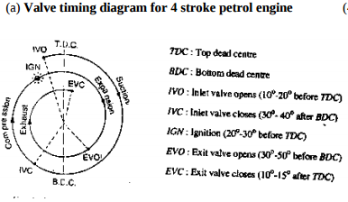 |
4 |
view | ||||||||||||
| Q 3 a ) |
Question:
Draw a neat labelled sketch of “Multiplate Clutch”. Answer:
 |
4 |
view | ||||||||||||
| Q 3 b ) |
Question:
Explain turb charging with a neat sketch. Answer:
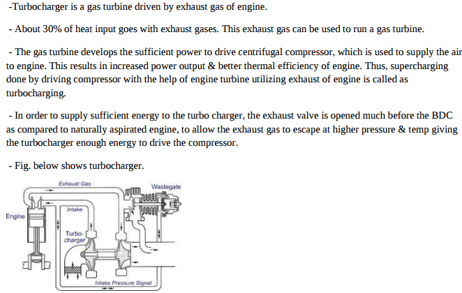 |
4 |
view | ||||||||||||
| Q 3 b ) |
Question:
Why roller follower is preferred over a knife follower ? State two advantages and application of roller follower. Answer:
|
4 |
view | ||||||||||||
| Q 3 c ) |
Question:
Explain three way catalytic convertor. Answer:
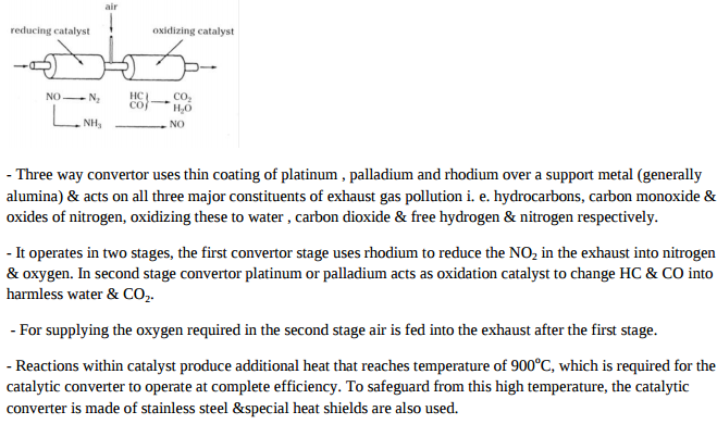 |
4 |
view | ||||||||||||
| Q 3 c ) |
Question:
Write the procedure for balancing of a single rotating mass by single masses rotating in the same plane. Answer:
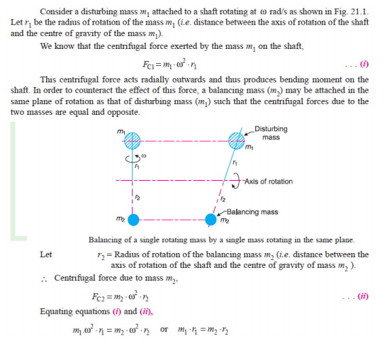 |
4 |
view | ||||||||||||
| Q 3 d ) |
Question:
Explain with a neat sketch turbo propeller w.r.to Jet propulsion Answer:
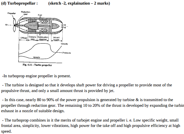 |
4 |
view | ||||||||||||
| Q 3 d ) |
Question:
State the type of power transmission chains. Describe any one with its sketch. Answer:
|
4 |
view | ||||||||||||
| Q 3 e ) |
Question:
Explain the concept of super heating and sub cooling with the help of P-h and T-s charts Answer:
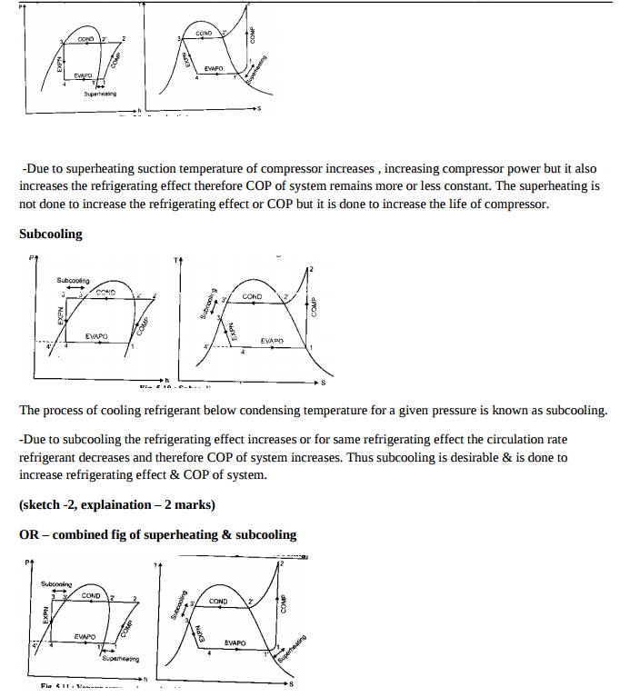 |
4 |
view | ||||||||||||
| Q 3 e ) |
Question:
PQRS is a four bar chain with PS fixed length of links are PQ = 62.5 mm, QR =175 mm, RS = 112.5 mm, PS = 200 mm. The crank PQ rotate at 10 rad/sec. in clockwise direction. Determine the angular velocity of point R, graphically by using relative velocity method.
Answer:
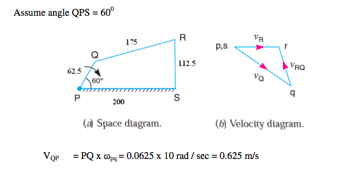 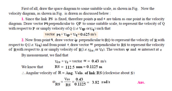 |
4 |
view | ||||||||||||
| Q 3 f ) |
Question:
Crank OA of a mechanism is hinged at ‘O’ and rotates at an angular velocity of 20 rad/sec. and angular acceleration of 25 rad/sec2 . If crank OA is 50 mm long determine linear velocity, centripetal acceleration and tangential acceleration of a point A. Answer:
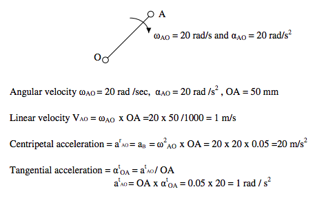 |
4 |
view | ||||||||||||
| Q 4 a ) |
Question:
What are the causes of detonation in I.C. engine ? Answer:
|
4 |
view | ||||||||||||
| Q 4 a ) |
Question:
Explain the phenomenon of slip and creep in a belt drive. State its effect on velocity ratio. Answer:
|
4 |
view | ||||||||||||
| Q 4 b ) |
Question:
What are the effects of pollutants on environment ? Answer:
|
4 |
view | ||||||||||||
| Q 4 b ) |
Question:
Explain with the diagram working of crank and slotted lever quick return mechanism. Answer:
|
4 |
view | ||||||||||||
| Q 4b)(a) |
Question:
Explain with neat sketch turning moment diagram for a four-stroke engine. Answer:
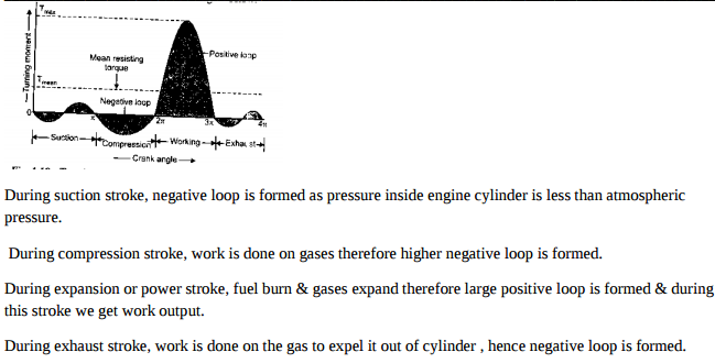 |
6 |
view | ||||||||||||
| Q 4b)(b) |
Question:
The following results were obtained during Morse test on 4-stroke petrol engine. B.P. developed when all cylinders are working = 16.2 kW. B.P. developed when cylinder No. 1 cutt off = 11.55 kW. B.P. developed when cylinder No. 2 cut off = 11.63 kW B.P. developed when cylinder No. 3 cut off = 11.68 kW B.P. developed when cylinder No. 4 cut off = 11.51 kW Calculate mechanical efficiency of engine. Answer:
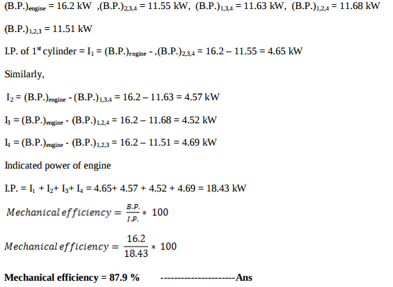 |
6 |
view | ||||||||||||
| Q 4 c ) |
Question:
Explain with sketch working of hartnell governor. Answer:
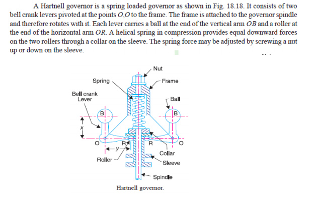 |
4 |
view | ||||||||||||
| Q 4 c ) |
Question:
What are the methods to improve thermal efficiency of gas turbine ? Explain any one method. Answer:
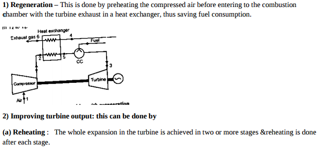 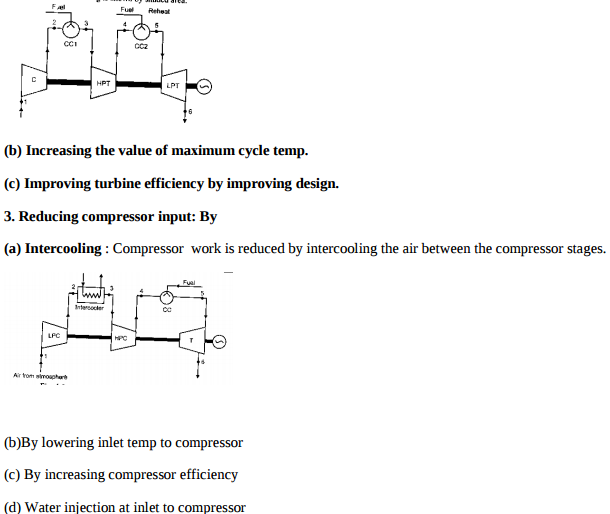 |
4 |
view | ||||||||||||
| Q 4 d ) |
Question:
Explain working of hydraulic brake dynamometer with sketch. Answer:
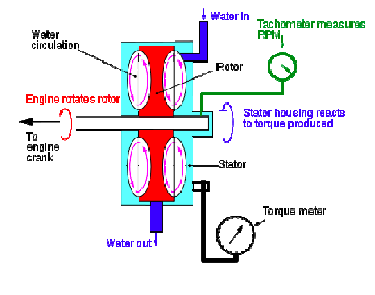 |
4 |
view | ||||||||||||
| Q 4 d ) |
Question:
What is jet propulsion ? Give the classification of jet propulsion system. Answer:
|
4 |
view | ||||||||||||
| Q 4 e ) |
Question:
Three masses 10 kg, 20 kg and 15 kg are attached at a point at radii of 20 cm, 25 cm and 15 cm respectively. If the angle between successive masses is 60° and 90°. Determine analytically the balancing mass to be attached at radius of 30 cm. Answer:
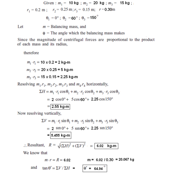 |
4 |
view | ||||||||||||
| Q 4 f ) |
Question:
A thrust shaft of a ship has 6 collar of 600 mm external diameter and 300 mm internal diameter. The total thrust from the propeller shaft is 100 kN. If the coefficient of friction is 0.12 and speed of engine 90 rpm. Find power absorbed in friction at the thrust block using uniform pressure intensity condition. Answer:
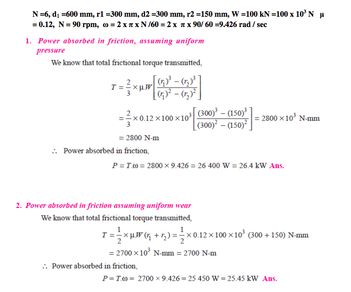 |
4 |
view | ||||||||||||
| Q 5 a ) |
Question:
Differentiate between reciprocating and rotary compressors Answer:
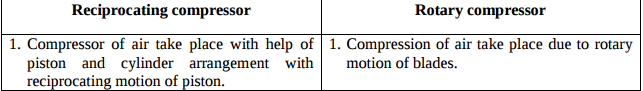 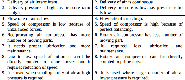 |
8 |
view | ||||||||||||
| Q 5 a ) |
Question:
In reciprocating engine the crank is 250 mm long and connecting rod is 1000 mm long. The crank rotate at 150 rpm. Find velocity and acceleration of piston and angular velocity and angular acceleration of connecting rod when the crank makes an angle of 30° to IDC. Use analytical method. Answer:
|
8 |
view | ||||||||||||
| Q 5 b ) |
Question:
Explain intercooling and reheating in gas turbine with the help of T-S diagram. Answer:
 LPC – LOW pressure cylinder HPC – high pressure cylinder CC – combustion chamber T – Turbine ( 2+ 2 marks) The net work of gas turbine cycle may be increased by saving some compression work. This is done by using several stages of compression with inter cooling of air between stages. The air from first stage of compression is cooled in inter cooler approximately to its initial temperature before entering to second stage of compressor. The effect of inter cooling is to decrease the network and increase the efficiency as compared to the simple ideal cycle without inter cooling. The ideal open gas turbine with inter cooling can be shown as 1 – 2 – 3 – 4 – 5 – 6 In first stage compressor atmospheric air is compressed from P1 to P2, it is them cooled from temperature T2 to T3 = T1 in the inter cooler at constant inter mediate pressure Px and finally compressed from Px to P2 in second stage or compressor. LPC – LOW pressure cylinder HPC – high pressure cylinder CC – combustion chamber T – Turbine ( 2+ 2 marks) The net work of gas turbine cycle may be increased by saving some compression work. This is done by using several stages of compression with inter cooling of air between stages. The air from first stage of compression is cooled in inter cooler approximately to its initial temperature before entering to second stage of compressor. The effect of inter cooling is to decrease the network and increase the efficiency as compared to the simple ideal cycle without inter cooling. The ideal open gas turbine with inter cooling can be shown as 1 – 2 – 3 – 4 – 5 – 6 In first stage compressor atmospheric air is compressed from P1 to P2, it is them cooled from temperature T2 to T3 = T1 in the inter cooler at constant inter mediate pressure Px and finally compressed from Px to P2 in second stage or compressor.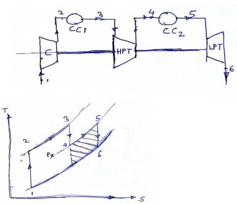 |
8 |
view | ||||||||||||
| Q 5 b ) |
Question:
Construct a cam profile with knife edge follower having an offset of 10 mm for the following data : Outstroke = 60° with SHM Dwell = 30° Return = 60° with uniform velocity and remaining is dwell period. Minimum radius of cam = 50 mm Lift of follower = 25 mm Consider the rotation of cam in clockwise direction. Answer:
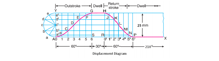 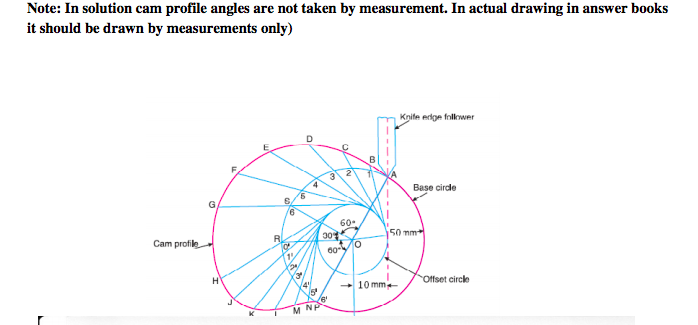 |
8 |
view | ||||||||||||
| Q 5 c ) |
Question:
Draw a neat sketch of vapour compression refrigeration cycle. Describe its working Answer:
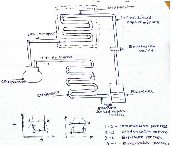 |
8 |
view | ||||||||||||
| Q 5 c ) |
Question:
A belt is required to transmit 10 kW from a motor running at 600 rpm. The belt is 12 mm thick and has a mass density 0.001 gm/mm3 . Safe stress in the belt is not to exceed 2.5 N/mm2 , diameter of the driving pulley is 250 mm whereas the speed of the driven pulley is 200 rpm. The two shafts are 1.25 m apart. The coefficient of friction is 0.25, determine (1) Angle of contact at driving pulley (2) The width of the belt Answer:
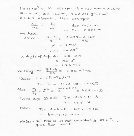 |
8 |
view | ||||||||||||
| Q 6 a ) |
Question:
What is MPFI ? Explain any one MPFI system with neat sketch. Answer:
|
4 |
view | ||||||||||||
| Q 6 a ) |
Question:
State the strength equations of double parallel fillet weld and single transverse fillet weld with neat sketches. Answer:
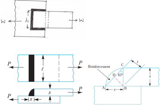 |
8 |
view | ||||||||||||
| Q 6a)(i) |
Question:
(i) Define ‘Gear Train’. State its purpose and types of gear train.
Answer:
|
4 |
view | ||||||||||||
| Q 6a)(ii) |
Question:
Explain the concept of fluctuation of energy related with turning moment diagram with sketch. Answer:
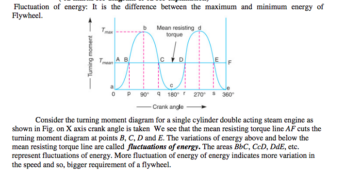 |
4 |
view | ||||||||||||
| Q 6 b ) |
Question:
A simple band brake is operated by lever 40 cm long. The brake drum diameter is 40 cm and brake band embrance 5/8 of its circumference. One end of band is attached to a fulcrum of lever while other end attached to pin 8 cm from fulcrum. The coefficient of friction 0.25. The effort applied at the end of lever is 500 N. Find braking torque applied if drum rotates anticlockwise and acts downwards. Answer:
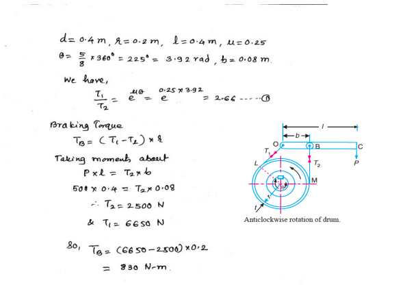 |
8 |
view | ||||||||||||
| Q 6 c ) |
Question:
Explain the working principle of jet propulsion with a neat sketch. Answer:
|
4 |
view | ||||||||||||
| Q 6 c ) |
Question:
An engine of a car has a single plate clutch developed maximum torque 147 N-m. External diameter of clutch plate is 1.2 times its internal diameter. Determine the dimension of clutch plate and axial force provided by the spring. The maximum pressure intensity of the clutch facing 98 kN/m2 and coefficient of friction is 0.3. Assume uniform wear condition. Answer:
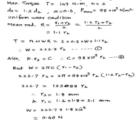 |
8 |
view | ||||||||||||
| Q 6 d ) |
Question:
Difference between Heat Pump and Refrigerator explain. Answer:
|
||||||||||||||
| HEAT PUMP | Refrigerator | ||||||||||||||
| 1) Heat pump is a device to maintain temperature of the system above the atmospheric temperature. | 1)Refrigerator is a device used to maintain the temperature of the system below the atmospheric temperature. | ||||||||||||||
| 2) Heat pump transfers heat energy from low temp thermal reservoir to High temperature thermal reservoir with the help of external work, with useful space is high temperature reservoir. | 2) A refrigerator transfers heat energy from low temperature reservoir to high temperature reservoir with the help of external work, the only difference is that the useful space is Low temperature reservoir. | ||||||||||||||
| 3) Evaporator is located outside room or external space. | 3) Evaporator is located inside room or internal space. | ||||||||||||||
| 4) Condenser is located inside room or internal space. | 4) Condenser is located outside room or external space. | ||||||||||||||
.png) |
.png) |
4 |
view | ||||||||||||
| Q 6 e ) |
Question:
Explain the working of window air conditioner with neat sketch. Answer:
|
4 |
view |
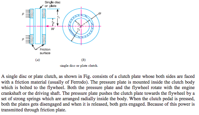
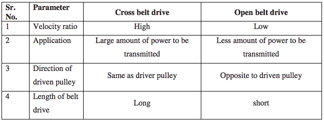

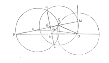
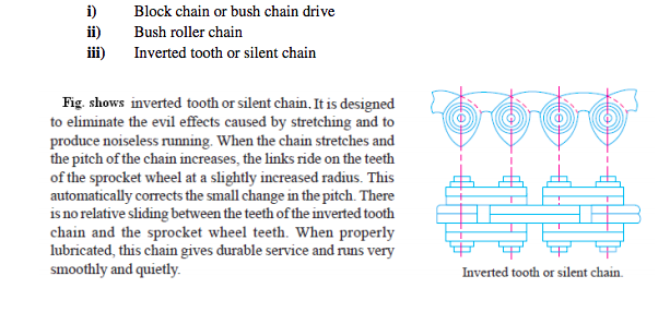
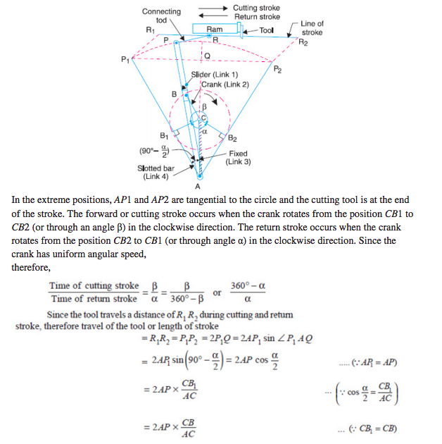
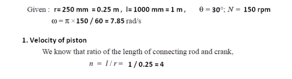
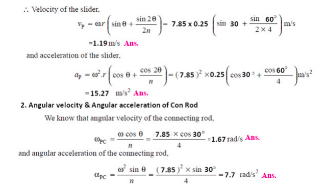
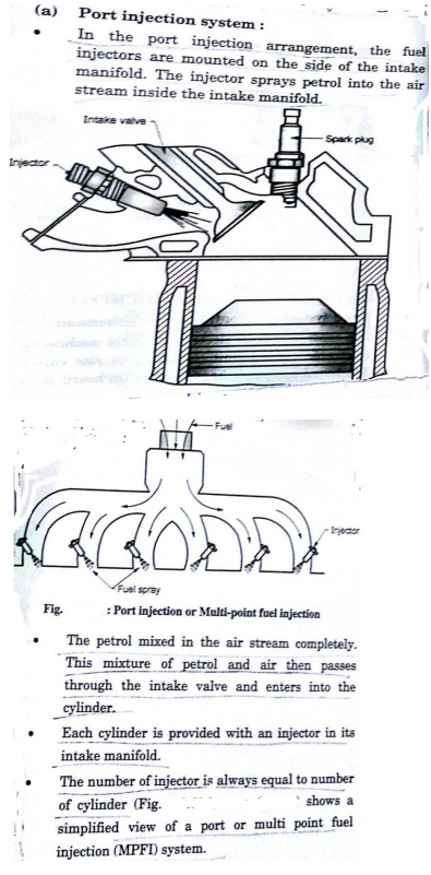
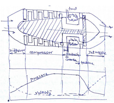
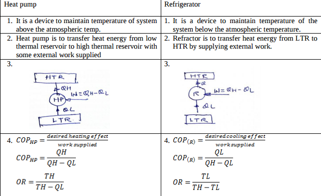
.png)
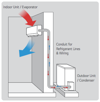
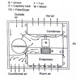
| Que.No | Question/Problem | marks | Link |
|---|---|---|---|
| Q 1a)(a) |
Question:
An engine of diameter 250 mm and 375 mm stroke works on otto cycle. The clearance volume is 0.00263 m3, find the air standard efficiency of cycle also sketch the cycle on P-V plane. Answer:
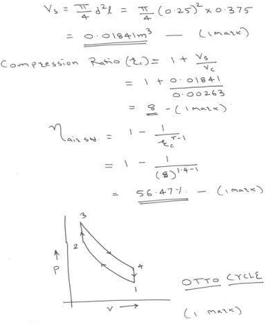 |
4 |
view |
| Q 1a)(b) |
Question:
State any four industrial uses of compressed air. Answer:
|
4 |
view |
| Q 1a)(c) |
Question:
Define the following terms related to compressor. i) Compressor capacity ii) Free air delivered iii) Volumetric efficiency iv) Mechanical efficiency Answer:
|
4 |
view |
| Q 1a)(d) |
Question:
What is pre-ignition ? State any two factors responsible for pre-ignition. Answer:
|
4 |
view |
| Q 1a)(i) |
Question:
Define - 1. Mechanism 2.Inversion Answer:
|
2 |
view |
| Q 1a)(ii) |
Question:
State any two types of motion of the follower.
Answer:
|
2 |
view |
| Q 1a)(ii) |
Question:
Differentiate between Knuckle joint and Cotter joint. (any four points of difference) Answer:
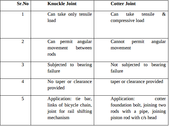 |
4 |
view |
| Q 1a)(iii) |
Question:
Define slip and creep in the belt. Answer:
|
2 |
view |
| Q 1a)(iii) |
Question:
Write Lewis equation for strength of gear tooth. State the meaning of each term Answer:
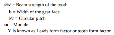 |
4 |
view |
| Q 1a)(iv) |
Question:
State any two advantages of V belt drive over flat belt drive. Answer:
|
2 |
view |
| Q 1a)(iv) |
Question:
State four different thread profiles used in power transmission. Draw neat sketches of any two of them. Answer:
|
4 |
view |
| Q 1a)(l) |
Question:
What are the steps involved in general design procedure? Explain. Answer:
|
4 |
view |
| Q 1a)(l) |
Question:
What is stress concentration? Explain any four methods to reduce it. Answer:
|
6 |
view |
| Q 1a)(v) |
Question:
State the function of flywheel in IC engine. Answer:
|
2 |
view |
| Q 1a)(vi) |
Question:
Define stability and hunting of governor. Answer:
|
2 |
view |
| Q 1a)(vii) |
Question:
Compare brakes and dynamometers (two points). Answer:
|
2 |
view |
| Q 1a)(viii) |
Question:
State any two adverse effects of imbalance. Answer:
|
2 |
view |
| Q 1b)(a) |
Question:
A petrol engine working on otto cycle has compression ratio 8 and consumes 1 kg of air per minute. If maximum temperature during the cycle is 2001 k and minimum temperature is 299 k. Find power developed by engine. Answer:
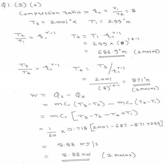 |
6 |
view |
| Q 1b)(b) |
Question:
Write any three pollutants in exhaust gasses of petrol and diesel engine with their effects on environment. Answer:
|
6 |
view |
| Q 1b)(i) |
Question:
Draw neat labeled sketch of crank and slotted lever mechanism. Label all parts. Answer:
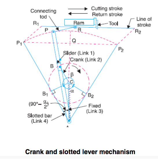 |
2 |
view |
| Q 1b)(ii) |
Question:
A shaft 1000 mm long is supported between two bearings. A pulley of 250 mm diameter is keyed at 400 mm distance away from left hand bearing. The power transmitted by shaft is 10 kW at 800 r.p.m. The pulley gives power to another pulley vertically below it having an angle of contact between pulley and belt as 180°. The weight of pulley is 300 N. The coefficient of friction between belt and pulley is 0.15. Take shear stress for shaft material as 60 MPa. Find the diameter of the shaft. Answer:
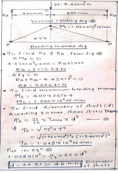 |
6 |
view |
| Q 1b)(ii) |
Question:
What is the necessity of clutch? State its types. Answer:
|
2 |
view |
| Q 1b)(iii) |
Question:
Draw the neat sketch of epicyclic gear train and explain how it works. Answer:
|
4 |
view |
| Q 2 a ) |
Question:
Explain the design procedure of handlever with neat sketch. Answer:
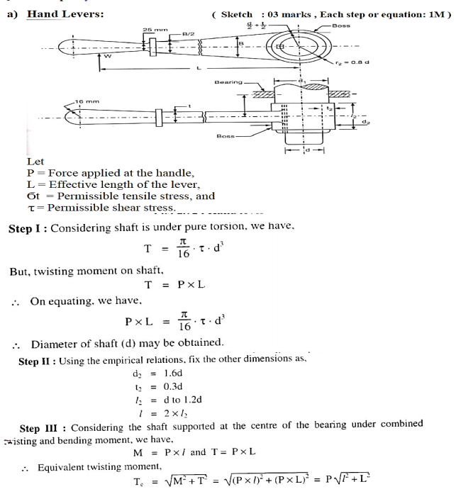 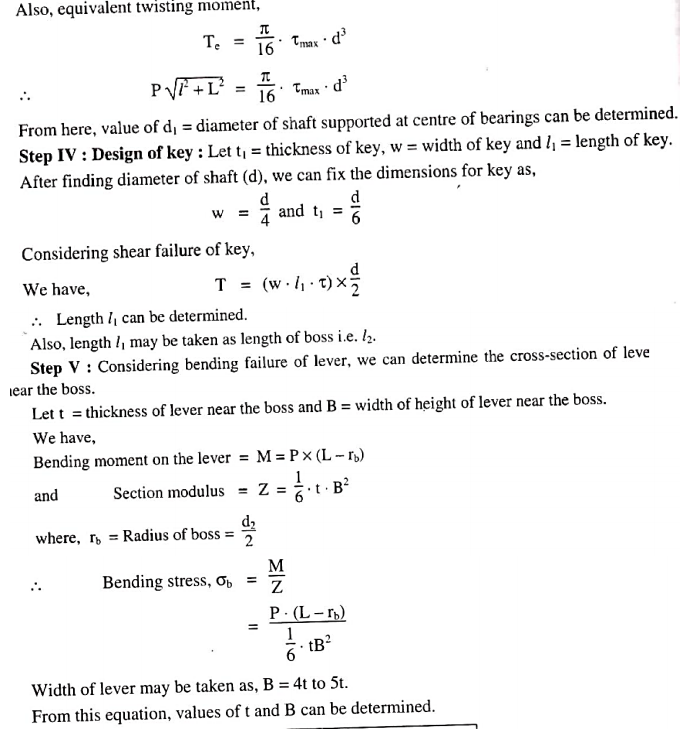 |
8 |
view |
| Q 2 a ) |
Question:
State and explain various types of constrained motions with suitable examples. Answer:
|
4 |
view |
| Q 2 a ) |
Question:
Compare Reciprocating air compressor and Rotary air compressor mentioning the basis of comparison (any 8 points) Answer:
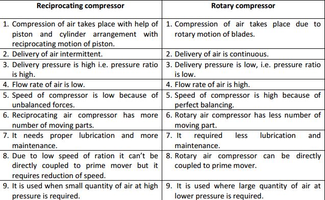 |
8 |
view |
| Q 2 b ) |
Question:
Explain sensible heating and cooling with dehumidification by sketching it on outline diagram of psychrometric chart Answer:
|
8 |
view |
| Q 2 b ) |
Question:
Explain the design procedure of bush pin type flexible coupling with neat sketch Answer:
|
8 |
view |
| Q 2 b ) |
Question:
Draw the neat labeled sketch of Oldham’s coupling. State its applications. Answer:
|
4 |
view |
| Q 2 c ) |
Question:
The following observations were made during the test on an oil engine BP of engine = 31.5 kW, fuel used = 10.5 kg/hr, C.V. of fuel = 43,000 kJ/kg, jacket circulating water = 540 kg/hr, rise in temperature of cooling water = 56°C, water circulated through exhaust gas calorimeter = 545 kg/hr, rise in temperature of water passing through exhaust gas calorimeter = 36°C, temperature of exhaust gas leaving the exhaust gas calorimeter = 82°C, A : F ratio = 19:1, ambient temperature = 17°C, Cp for exhaust gases = 1 kJ/kg°k. Draw up the heat balance sheet on minute basis. Answer:
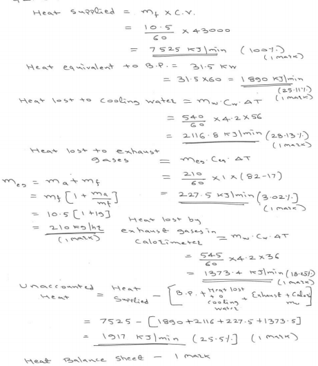 |
8 |
view |
| Q 2 c ) |
Question:
Define the terms linear velocity, relative velocity, angular velocity and angular acceleration. Answer:
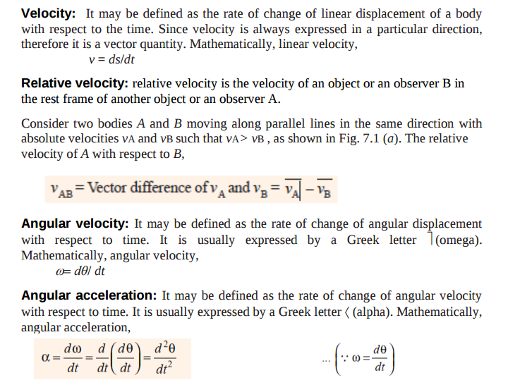 |
4 |
view |
| Q 2c)(i) |
Question:
Explain with neat sketch the stress-strain diagram for ductile material. Answer:
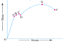 |
8 |
view |
| Q 2c)(ii) |
Question:
Design ‘‘C’’ clamp frame for a total clamping force of 20 kN. The cross-section of the frame is rectangular and width to thickness ratio is 2. The distance between the load line and natural axis of rectangular cross section is 120 mm and the gap between two faces is 180 mm. The frame is made of cast steel for which maximum permissible tensile stress is 100 N/mm Answer:
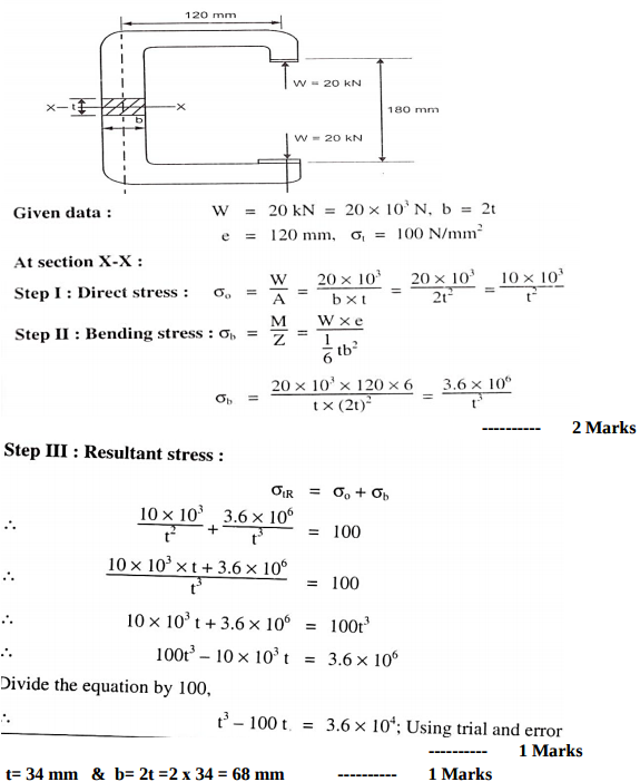 |
8 |
view |
| Q 2 d ) |
Question:
For a single slider crank mechanism , state the formulae to calculate by analytical method – Also state the meaning of each term. Answer:
|
4 |
view |
| Q 2 e ) |
Question:
Define the following terms related to cams. Answer:
|
4 |
view |
| Q 2 f ) |
Question:
A casting weighing 9 kN hangs freely from a rope which makes 2.5 turns round a drum of 300 mm diameter revolving at 20 rpm. The other end of the rope is pulled by a man. Taking μ = 0.25, determine (i) the force required by the man (ii) the power to raise the casting.
Answer:
|
4 |
view |
| Q 3 a ) |
Question:
What is catalytic convertor ? Explain two way catalytic convertor with neat sketch Answer:
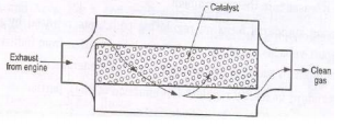 |
4 |
view |
| Q 3 a ) |
Question:
State the composition of following materials (i) Fe E 230 (ii) X 20 Cr 18 Ni 2 (iii) 35 C 8 (iv) 40 Ni 2 Cr 1 Mo 28 Answer:
|
4 |
view |
| Q 3 a ) |
Question:
Space diagram 01 Mark, Velocity Diagram 02 marks , Calculations 01 Mark Note In QP length BC & AB are equal. Read length AD = length BC = 150 mm Answer:
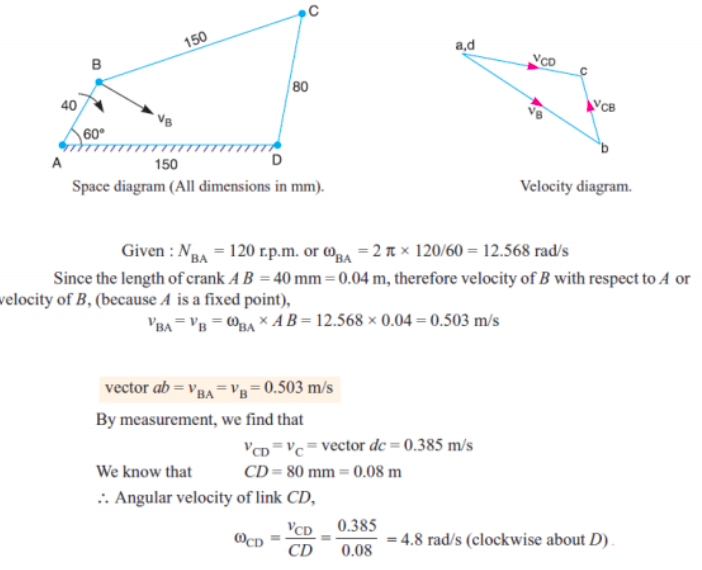 |
4 |
view |
| Q 3a)(d) |
Question:
Describe the method to measure indicated power of I.C. engine. Answer:
|
4 |
view |
| Q 3 b ) |
Question:
Draw constant pressure closed cycle gas turbine on P.V and T-S planes. Name the various processes involved and give its efficiency equation with meaning of each term. Answer:
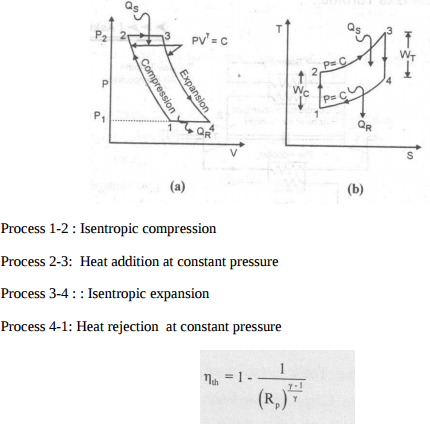 |
4 |
view |
| Q 3 b ) |
Question:
Design an offset link for a load of 1000 N. Maximum permissible stress in tension for link material is 60 N/mm2. Assume b = 3t for rectangular cross section of the link. Answer:
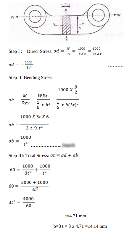 |
4 |
view |
| Q 3 b ) |
Question:
In a single slider crank mechanism, crank AB = 20 mm and connecting rod BC = 80 mm. Crank AB rotates with uniform speed of 1000 rpm in anticlockwise direction. Find (i) angular velocity of connecting rod BC and (ii) Velocity of slider C when crank AB makes angle of 60° with the horizontal. Answer:
|
4 |
view |
| Q 3 c ) |
Question:
Draw and explain simple vapour absorption refrigeration system Answer:
|
4 |
view |
| Q 3 c ) |
Question:
Prove that for square key equally strong in shear and crushing, the permissible crushing stress is twice the permissible shear stress Answer:
|
4 |
view |
| Q 3 c ) |
Question:
State the formulae to calculate the length of open belt drive and cross belt drive. State the meaning of each term by drawing suitable diagrams in both cases. Answer:
|
4 |
view |
| Q 3 d ) |
Question:
Name the different sensors used in ECU of modern automobile with their application. (minimum 4 Answer:
|
4 |
view |
| Q 3 d ) |
Question:
Explain with neat sketch the bolts of uniform strength. Answer:
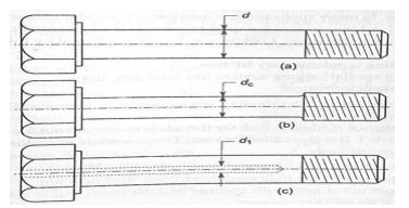 |
4 |
view |
| Q 3 d ) |
Question:
Draw the neat sketch of single plate clutch and explain its working. Answer:
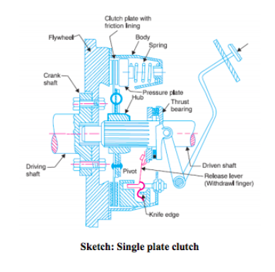 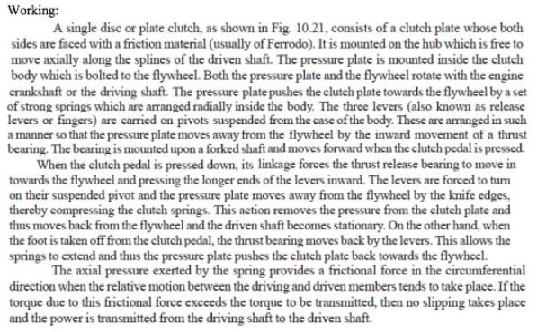 |
4 |
view |
| Q 3 e ) |
Question:
Explain different stages of combustion in C.I. engine with sketch. Answer:
|
4 |
view |
| Q 3 e ) |
Question:
How keys are classified? Give detailed classification of keys with neat sketches; also state their applications. Answer:
|
4 |
view |
| Q 3 e ) |
Question:
State the procedure of balancing single rotating mass when its balancing mass is rotating in the same plane as that of disturbing mass. Answer:
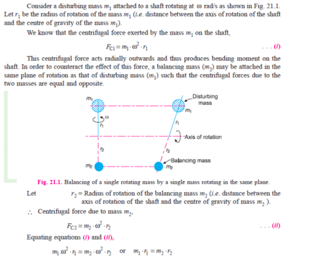 |
4 |
view |
| Q 3 f ) |
Question:
Give detailed classification of followers. Answer:
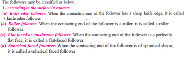 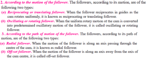 |
4 |
view |
| Q 4 a ) |
Question:
What is centrifugal tension ? State its formula. Explain its effect on power transmitted by a belt drive. Answer:
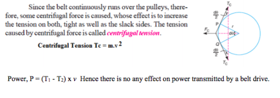 |
4 |
view |
| Q 4a)(a) |
Question:
Explain MPFI system with sketch Answer:
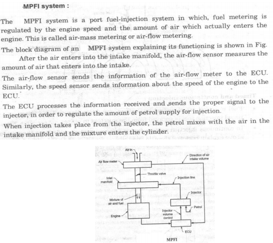 |
4 |
view |
| Q 4a)(b) |
Question:
Define the following related I.C. engine. i) Indicated power ii) Brake power iii) Brake specific fuel consumption iv) Relative efficiency. Answer:
|
4 |
view |
| Q 4a)(c) |
Question:
Draw and explain Battery ignition system. Answer:
|
4 |
view |
| Q 4a)(ii) |
Question:
Answer:
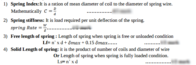 |
4 |
view |
| Q 4a)(iv) |
Question:
A cylinder head of steam engine is held in position by M20 bolts. The effective diameter of cylinder is 350 mm and the steam pressure is 0.75 N/mm2. If the bolts are not initially stressed, find the number of bolts required. Take working stress for bolt material as 20 N/mm2. Answer:
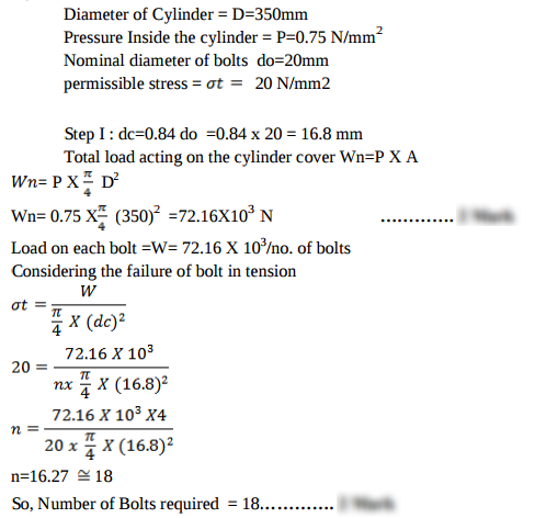 |
4 |
view |
| Q 4a)(l) |
Question:
State the meaning of following colour codes in aesthetic consideration while designing the product: (1) Red (2) Orange (3) Green (4) Blue Answer:
|
4 |
view |
| Q 4 b ) |
Question:
State the meaning of sliding pair, turning pair, rolling pair and spherical pair with one example each. Answer:
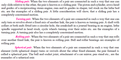 |
4 |
view |
| Q 4b)(a) |
Question:
List the additives of Lubricant used in S.I. engine and state their advantages. Answer:
|
6 |
view |
| Q 4b)(b) |
Question:
Explain working of 4 stroke S.I. engine with neat sketch. or With neat sketches explain the working principle of four stroke spark ignition engine. Answer:
|
6 |
view |
| Q 4b)(i) |
Question:
State the different modes of failure of gear teeth and their possible remedies to avoid the failure. Answer:
|
6 |
view |
| Q 4b)(ii) |
Question:
Explain the following types of stresses: (1) Transverse shear stress (2) Compressive stress (3) Torsional shear stress Answer:
|
6 |
view |
| Q 4 c ) |
Question:
Draw turning moment diagram for single cylinder four stroke I.C. Engine. Label all parts. Answer: |
4 |
view |
| Q 4 d ) |
Question:
Explain the working of rope brake dynamometer with neat sketch. Answer:
 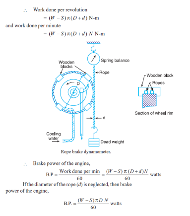 |
4 |
view |
| Q 4 e ) |
Question:
A vertical shaft 150 mm in diameter and rotating at 100 rpm rests on a flat end footstep bearing. The shaft carries vertical load of 20 kN. Assuming uniform pressure distribution and coefficient of friction equal to 0.05, estimate power lost in friction Answer:
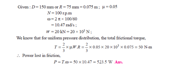 |
4 |
view |
| Q 4 f ) |
Question:
Four masses m1, m2, m3 and m4 are 200 kg, 300 kg, 240 kg, and 260 kg respectively. The corresponding radii of rotation are 0.2 m, 0.15 m, 0.25 m and 0.3 m respectively and the angles between successive masses are 45°, 75° and 135°. Find the position and magnitude of balance mass required, if its radius of rotation is 0.2 m. Answer:
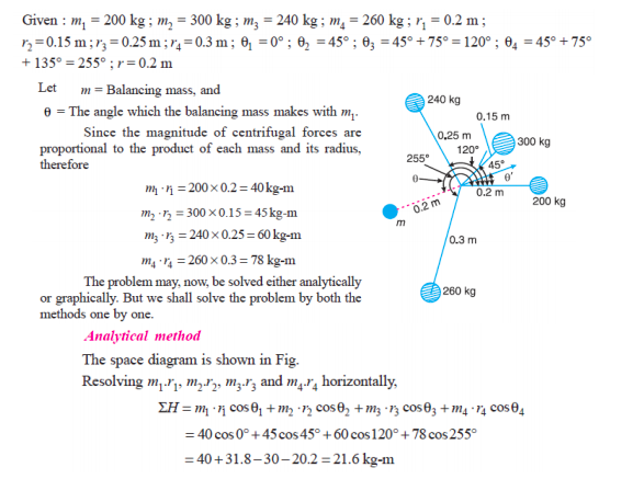 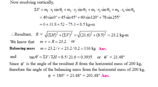 |
4 |
view |
| Q 5 a ) |
Question:
The crank and connecting rod of a reciprocating engine are 200 mm and 700 mm respectively. The crank is rotating in clockwise direction at 120 rad/s. Draw Klein’s construction and find (i) Velocity and acceleration of the piston (ii) Angular velocity and angular acceleration of the connecting rod at the instant when the crank is at 30° to IDC (inner dead centre). Answer:
|
4 |
view |
| Q 5 a ) |
Question:
A vertical double start square threaded screw of 120 mm mean diameter and 24 mm pitch supports a vertical load of 20 kN. The axial thrust in screw is taken by collar bearings of 300 mm outside and 150 mm inside diameter. Find the force required at the end of the lever which is 400 mm long in order to lift and lower the load. The coefficient of friction for screw and nut is 0.18 and for collar bearing it is 0.25. Answer:
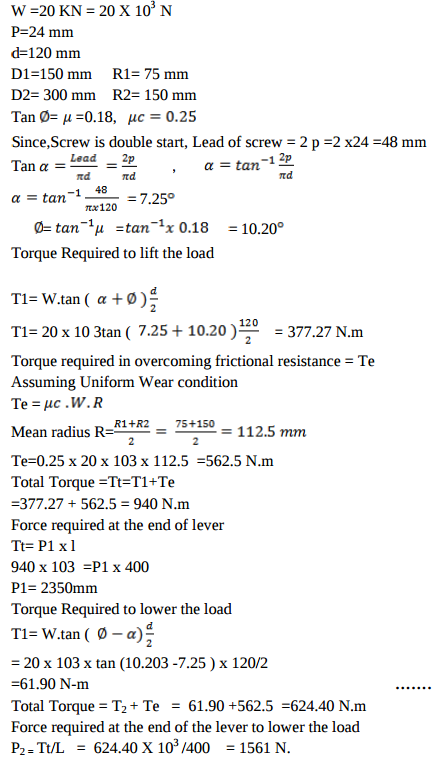 |
8 |
view |
| Q 5 a ) |
Question:
Explain construction and working of ice plant with neat sketch. Answer:
|
8 |
view |
| Q 5 b ) |
Question:
A cam is to give the following motion to a knife edged follower : (i) Outstroke during 60° of cam rotation. (ii) Dwell for the next 30° of cam rotation. (iii) Return stroke during next 60° of cam rotation. iv) Dwell for the remaining 210° of cam rotation. The stroke of the follower is 40 mm and the minimum radius of the cam is 50 mm. The follower moves with uniform velocity during both the outstroke and return stroke. Draw the profile of the cam when the axis of the follower passes through the axis of the camshaft. Answer:
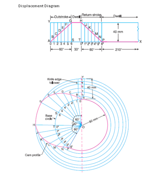 |
8 |
view |
| Q 5 b ) |
Question:
A safety valve of 60 mm diameter is to blow off at a pressure of 1.2 N/mm2. It is held on its seat by a close coiled helical spring. The maximum lift of the valve is 10 mm. Design a suitable compression spring of spring index 5 with an initial compression of 35 mm. The shear stress for spring material is limited to 500 MPa. Take G = 80 kN/mm2. Answer:
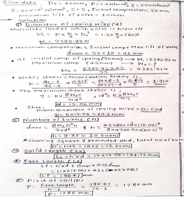 |
8 |
view |
| Q 5 b ) |
Question:
A pneumatic rock drill requires 10 kg/min of air at 6 bar pressure. Find the power required to drive the single acting single stage reciprocating compressor receiving air at 1 bar and 27°C. Assume mechanical efficiency as 80% and value of index, n as 1.25. Take Cp = 1.005 kJ/kgk and Cv = 0.718 kJ/kgk for air. Also estimate isothermal efficiency of compression. Answer:
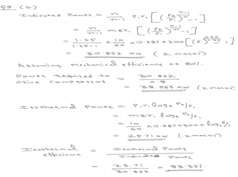 |
8 |
view |
| Q 5 c ) |
Question:
Two parallel shafts whose centre line are 4.8 m apart, are connected by open belt drive. The diameter of larger pulley is 1.5 m and that of smaller pulley 1 m. The initial tension in the belt when stationary is 3 kN. The mass of the belt is 1.5 kg/m length. The coefficient of friction between the belt and pulley is 0.3 Taking centrifugal tension into account, calculate the power transmitted when the smaller pulley rotates at 400 rpm. Answer:
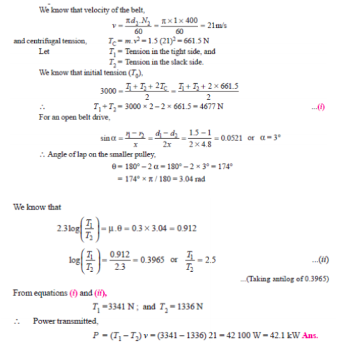 |
8 |
view |
| Q 5 c ) |
Question:
Explain construction and working of turbojet with neat labelled sketch Answer:
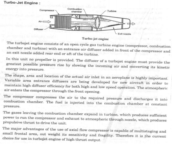 |
4 |
view |
| Q 5c)(ii) |
Question:
Explain the terms self locking and overhauling of screw. Answer:
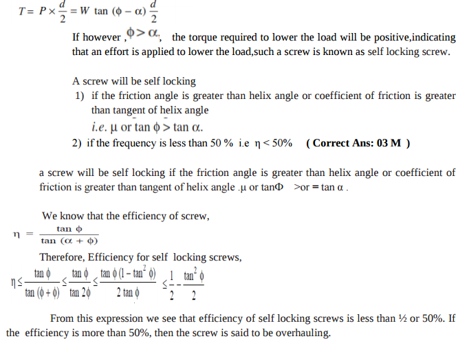 |
8 |
view |
| Q 5c)(l) |
Question:
Differentiate between sliding contact and rolling contact bearings. (any four points of difference) Answer:
 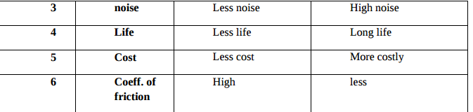 |
6 |
view |
| Q 6 a ) |
Question:
Represent subcooling and superheating on P-h and T-S diagram in refrigeration also give its effect on C.O.P. of refrigeration. Answer:
|
4 |
view |
| Q 6a)(i) |
Question:
State and explain law of gearing with the help of suitable sketch. Answer:
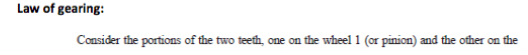 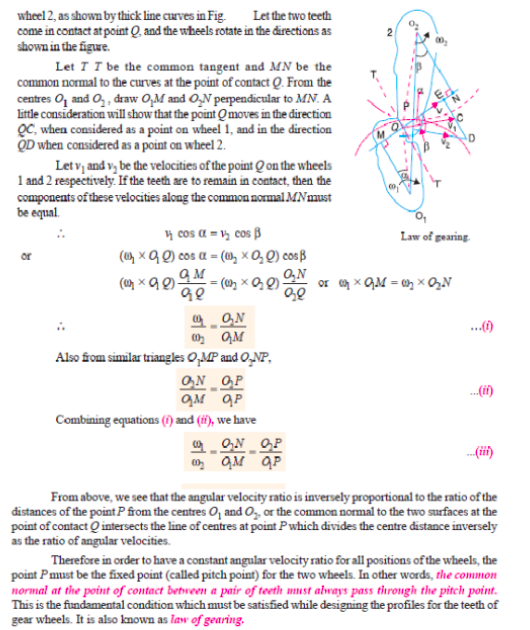 |
4 |
view |
| Q 6a)(ii) |
Question:
Compare flywheel and governor. Answer:
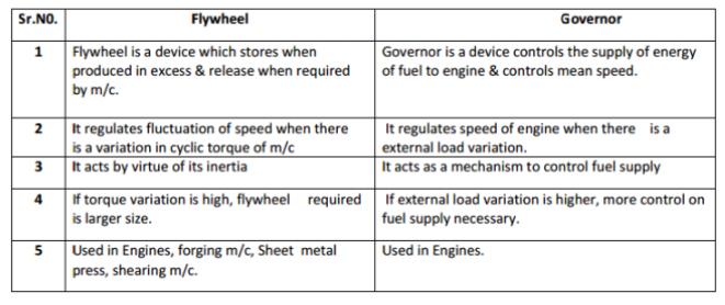 |
4 |
view |
| Q 6 b ) |
Question:
In a simple band brake, the band acts on the 3/4th of circumference of a drum of 450 mm diameter which is keyed to the shaft. The band brake provides a braking torque of 225 N.m. One end of the band is attached to a fulcrum pin of the lever and the other end to a pin 100 mm from the fulcrum. It the operating force is applied at 500 mm from the fulcrum and the coefficient of friction is 0.25, find the operating force when the drum rotates in the (i) anticlockwise direction and ii) clockwise direction Answer:
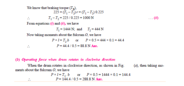 |
8 |
view |
| Q 6 b ) |
Question:
A semi-elliptical carriage spring of 1200 mm length withstands a load of 60 kN with maximum deflection of 90 mm. Assume breadth to thickness ratio as 8. Design the spring if bending stress of spring material is 540 MPa and E = 2 × 10⁵ N/mm2. Answer:
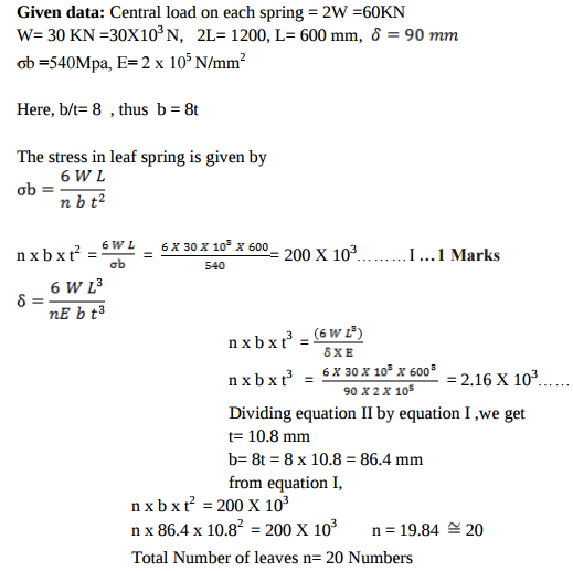 |
8 |
view |
| Q 6 b ) |
Question:
Define perfect and imperfect inter-cooling in air compressor and show it by graph also Answer:
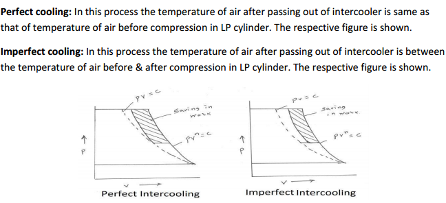 |
4 |
view |
| Q 6 c ) |
Question:
A single plate clutch with both sides effective has outer and inner diameters 300 mm and 200 mm respectively. The maximum intensity of pressure at any point in the contact surface is not to exceed 0.1 N/mm2. If the coefficient of friction is 0.3, determine the power transmitted by a clutch at a speed of 2500 rpm. Assume uniform condition. Answer:
|
8 |
view |
| Q 6 c ) |
Question:
A wall bracket is fixed to the wall by means of three bolts, one bolt at a distance of 25 mm from the lower edge and remaining two bolts at a distance of 175 mm from the lower bolts. It supports a load of 7.5 kN at a distance of 250 mm from the wall. The bolts are made from plain carbon steel 45C8 with tensile yield strength of 380 N/mm2. If factor of safety is 2.5, estimate the size of the bolts. Sketch the arrangement Answer:
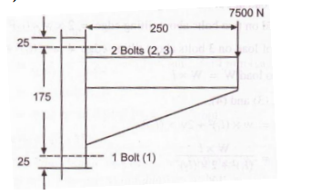 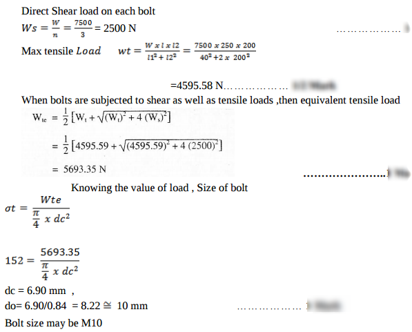 |
8 |
view |
| Q 6 c ) |
Question:
Draw P-V and T-S diagram for dual cycle. Name the processes involved in it. Answer:
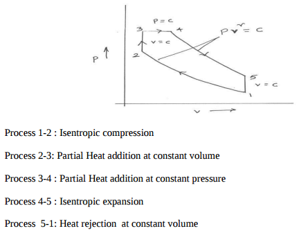 |
4 |
view |
| Q 6 d ) |
Question:
Give classification of air conditioning system. Answer:
|
4 |
view |
| Q 6 d ) |
Question:
Explain the selection procedure of bearings from manufacturer’s catalogue. Answer:
|
8 |
view |
| Q 6 e ) |
Question:
Compare, closed cycle and open cycle gas turbine (any four point) Answer:
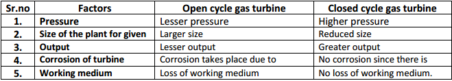 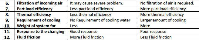 |
4 |
view |
| Q 6 e ) |
Question:
State the applications of following bearings with suitable reasons: (i) Deep grove ball bearing (ii) Taper roller bearing (iii) Thrust coller bearing (iv) Needle roller bearing Answer:
|
8 |
view |
| Q 6 f ) |
Question:
State the different methods used to improve thermal efficiency of gas turbine. Explain any one in brief. Answer:
|
4 |
view |
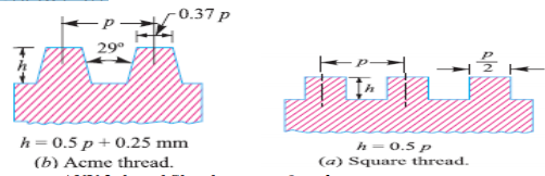
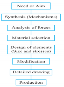
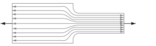
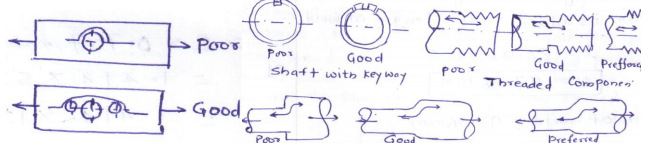
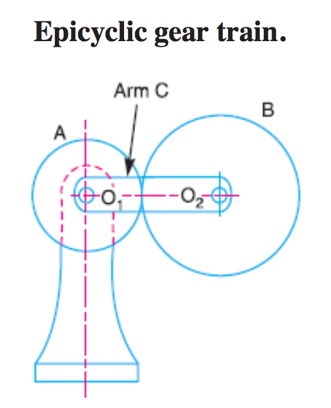
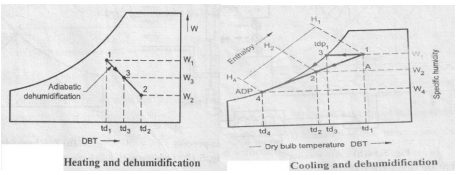
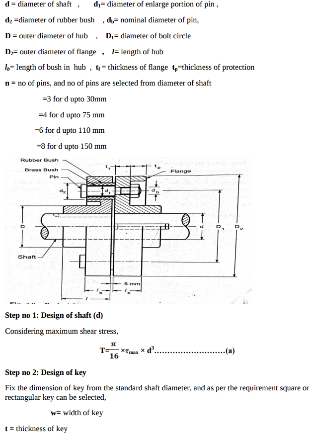
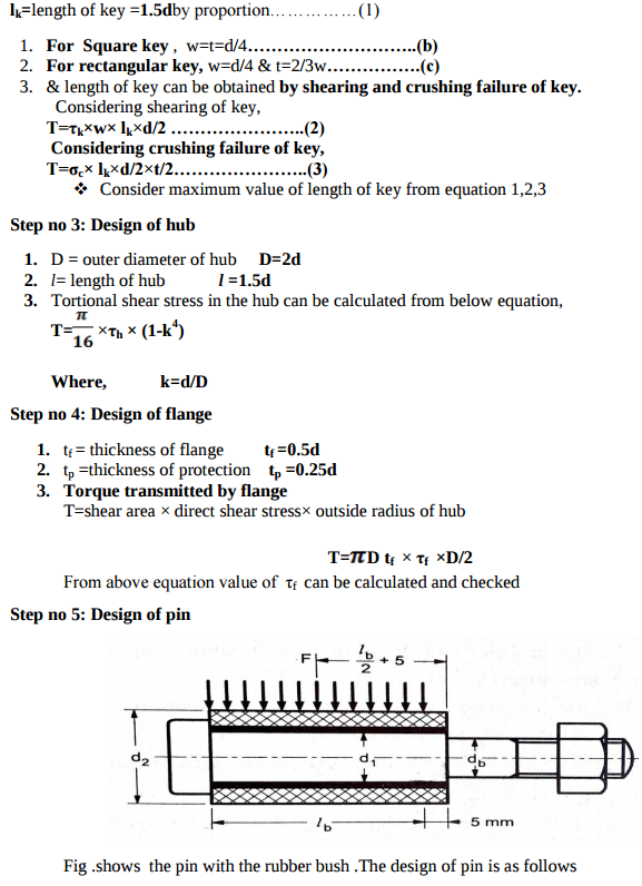
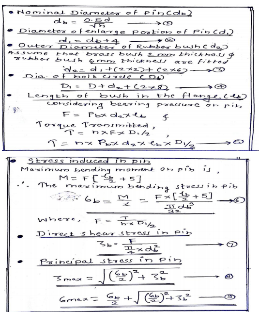
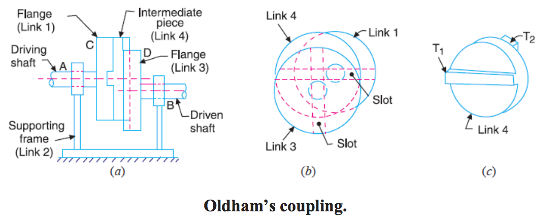
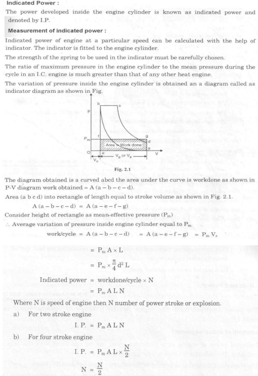
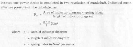
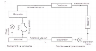
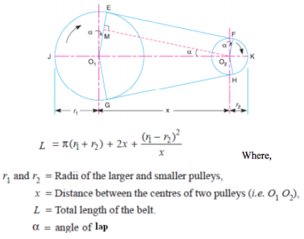
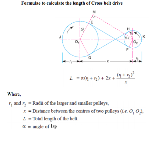
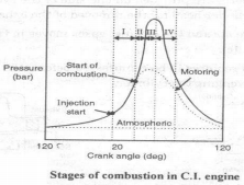
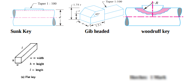
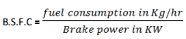
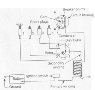
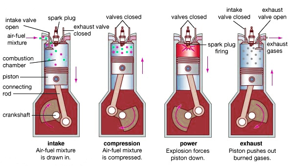
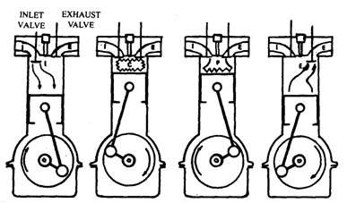
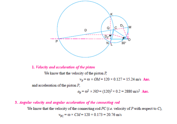
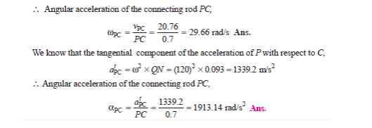
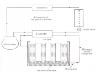
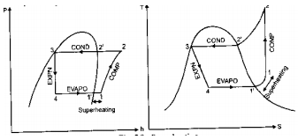
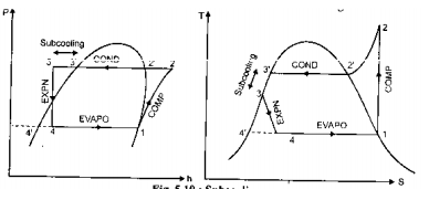
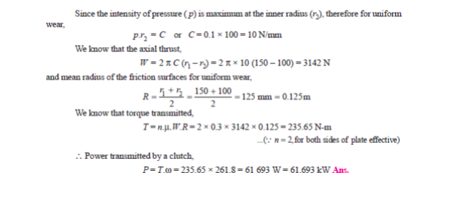
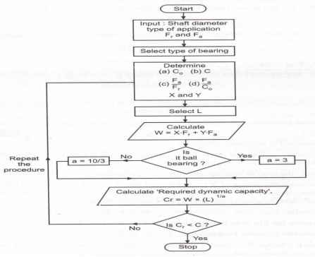
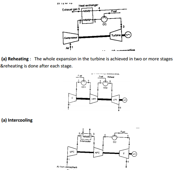
| Que.No | Question/Problem | marks | Link |
|---|---|---|---|
| Q 1a)(i) |
Question:
Why does the Carnot heat engine not exist in practice? Give any four points Answer:
|
4 |
view |
| Q 1a)(ii) |
Question:
Define following efficiencies related to compressors: 1) mechanical efficiency 2) polytropic efficiency 3) compressor efficiency 4) overall volumetric efficiency Answer:
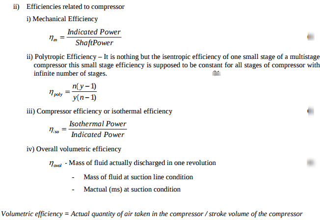 |
4 |
view |
| Q 1a)(iii) |
Question:
Show the effect of increase of compression ratio in a single stage reciprocating compresor on PV diagram and give its physical significance. Answer:
|
4 |
view |
| Q 1a)(iv) |
Question:
Compare the effect of supercharging on S.I. engine and C.I. engine with respect to following parameters: 1) detonation 2) combustion 3) fuel economy 4) quality of fuel. Answer:
|
4 |
view |
| Q 1b)(i) |
Question:
What do you mean by: 1) frictional power 2) brake thermal efficiency 3) BSFC, w.r.to I.C. engine Answer:
|
6 |
view |
| Q 1b)(ii) |
Question:
Explain with neat sketch any one catalytic converter Answer:
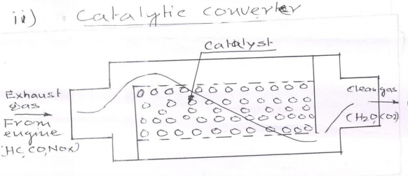 |
6 |
view |
| Q 2a)(i) |
Question:
The criterion of the thermodynamic efficiency of a reciprocating compressor is isothermal compression while for rotory compressor it is isentropic compression. Discuss the reason for this. Answer:
|
8 |
view |
| Q 2a)(ii) |
Question:
Compare reciprocating compressors and centrifugal compressors on the basis of the following parameters: 1) adaptability 2) suitability 3) mechanical efficiency 4) capacity of delivering volume. Answer:
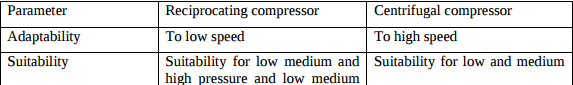 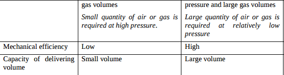 |
8 |
view |
| Q 2b)(i) |
Question:
Define: 1) DPT 2) WBT 3) DBT 4) moist air. Answer:
|
8 |
view |
| Q 2b)(ii) |
Question:
Define following terms: 1) specific humidity 2) absolute humidity 3) relative humidity 4) degree of saturation. Answer:
|
8 |
view |
| Q 2 c ) |
Question:
During a trial on 4-stroke gas engine following observations were recorded: Bore = 300 mm ; Speed = 200 rpm Stroke = 400 mm ; Gas used = 11.7 m3/h Number of explosions/min = 90 Gauge pressure of gas = 170 mm of water Barometer reading = 755 mm of Hg Mean effective pressure = 6 bar Calorific value of gas used = 21500 KJ/kg at N.T.P. Net load on brake = 2 KN Brake drum diameter = 1.2 m Ambient temperature = 27°C Calculate: (i) mechanical efficiency (ii0 brake thermal efficiency. Answer:
|
8 |
view |
| Q 3 a ) |
Question:
The results of exhaust gas analysis for petrol engine running at full load and at constant speed are shown in Fig. No. 1. Label the exhaust gases (indicated by 1, 2, 3, 4). Which conclusion can be drawn from this figure.
Answer:
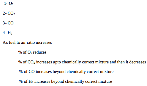 |
4 |
view |
| Q 3 b ) |
Question:
State merits/demerits of gas turbine over T.C. engine with respect to following parameters: (i) mechanical efficiency (ii) starting trouble (iii) weight per power (iv) part load thermal efficiency. Answer:
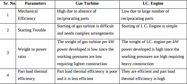 |
4 |
view |
| Q 3 c ) |
Question:
List any four applications of refrigeration. Answer:
|
4 |
view |
| Q 3 d ) |
Question:
Draw super imposed PV and TS diagrams of otto cycle, diesel cycle and dual cycle to compare their efficiencies under the following conditions: (i) for same compression ratio and heat rejection (ii) for same maximum pressure and temperature and heat rejection. Answer:
|
4 |
view |
| Q 3 e ) |
Question:
Draw P-V and T-S diagram for carnot cycle. Name the processes involved in it. Answer:
|
4 |
view |
| Q 4a)(ii) |
Question:
Define cut off ratio. Express it in terms of compression ratio and expansion ratio. Answer:
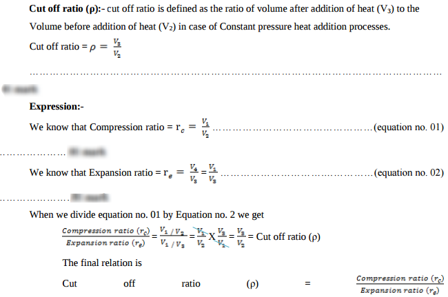 |
4 |
view |
| Q 4a)(iii) |
Question:
Differentiate between L-MPFI system and D-MPFI system. Answer:
 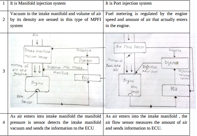 |
4 |
view |
| Q 4a)(iv) |
Question:
Various efficiencies of 4-stroke petrol engine run at full throttle over its speed range are plotted in Fig. No. 2. Label different efficiency curves (indicated by 1, 2, 3, 4). Which conclusion can be drawn from this figure.
Answer:
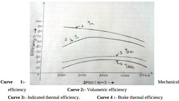 |
4 |
view |
| Q 4a)(l) |
Question:
State the functions of following components used in battery ignition system: 1) capacitor 2) ballast register 3) contact breaker 4) distributor Answer:
|
4 |
view |
| Q 4b)(ii) |
Question:
Draw theoretical and actual P-V diagrams for S.I. engines and explain briefly Answer:
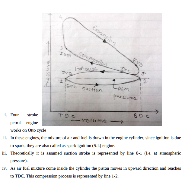 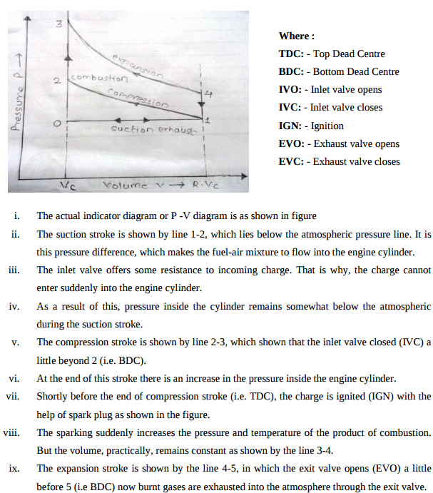 |
6 |
view |
| Q 4b)(l) |
Question:
State the role of following lubricant additives: 1) zinc ditinophosphate 2) fatty acids 3) organic acids 4) ester 5) silicone polymers 6) butylene polymers. Answer:
|
6 |
view |
| Q 5 a ) |
Question:
Answer:
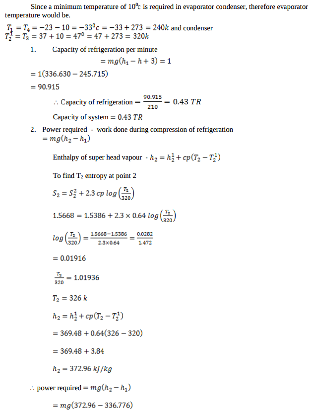 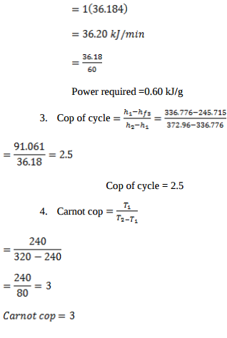 |
8 |
view |
| Q 5 b ) |
Question:
A single stage single acting air compressor delivers 0.6 kg of air per minute at 6.1 bar. The temperature and presure at the end of suction stroke are 28°C and 1.1 bar. The bore and stroke of the compressor are 100 mm and 150 mm respectively. The clearance is 3 % of the swept volume. Assuming index of compression and expansion as 1.25, find: (i) volumetric efficiency of compressor (ii) power required if mechanical efficiency is 85% (iii) speed of compressor in rpm Answer:
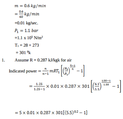 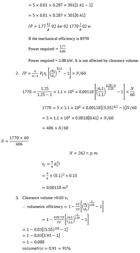 |
8 |
view |
| Q 5 c ) |
Question:
Explain the construction and working of Ram jet with the help of neat labelled schematic diagram. State its limitations (any two). Answer:
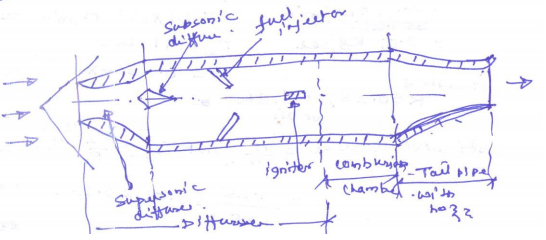 |
8 |
view |
| Q 6 a ) |
Question:
Which is more effective way to increse the C.O.P. of refrigerator, to increase T2 keeping T1 constant or to decrease T1 keeping T2 constant? (T1 > T2). Give justification to your answer. Answer:
 |
4 |
view |
| Q 6 b ) |
Question:
Define displacement of compressor for two stage compressor. Why is free air delivered less than displacement of compressor? Answer:
|
4 |
view |
| Q 6 c ) |
Question:
An engine working on otto cycle has, d = 150 mm, L = 225 mm υc = 1.25 × 10⁻³ m3. Find air standard efficiency. Answer:
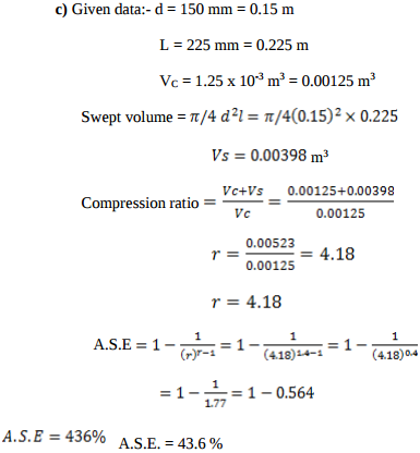 |
4 |
view |
| Q 6 d ) |
Question:
Distinguish between central A/C and unitary A/C systems with respect to following parameters: (i) vibration (ii) noise (iii) power consumption (iv) operating cost (v) ducting (vi) failure problem (vii) initial cost (viii) maintenance cost Answer:
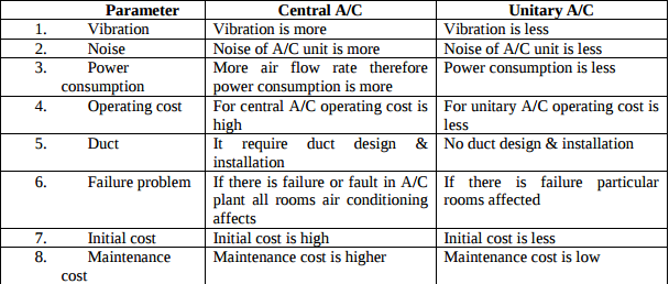 |
4 |
view |
| Q 6 e ) |
Question:
In gas turbine plants, Brayton cycle is more suitable than otto cycle, even though both cycles have equal thermal efficiency for same compression ratio. Justify Answer:
|
4 |
view |
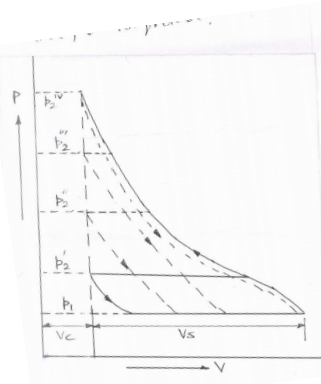
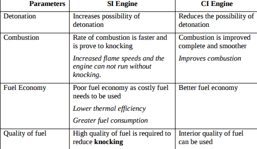
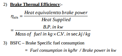
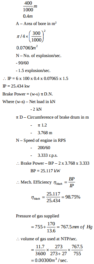
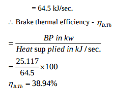
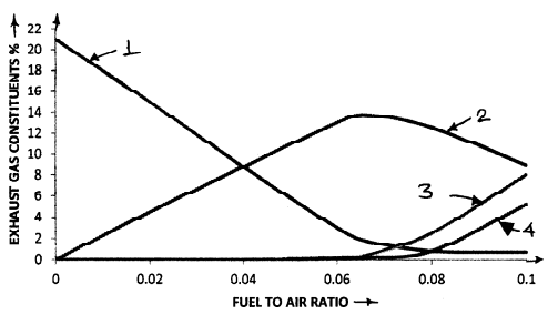
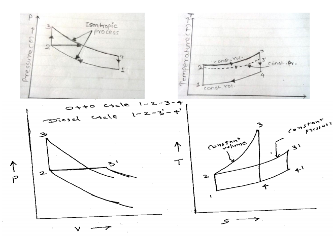
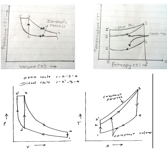
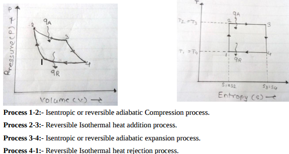
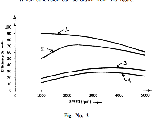
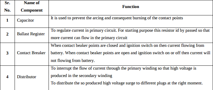
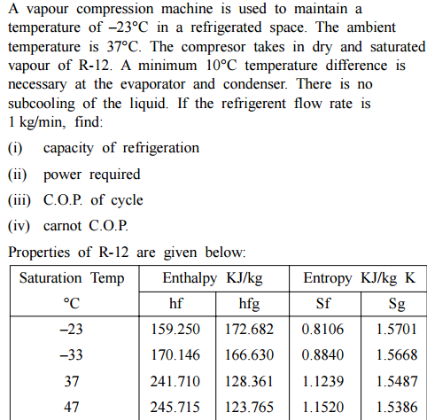
| Que.No | Question/Problem | marks | Link |
|---|---|---|---|
| Q 1a)(a) |
Question:
Draw P-V and T-S diagram for Diesel cycle. Name the processes involved in it. Answer:
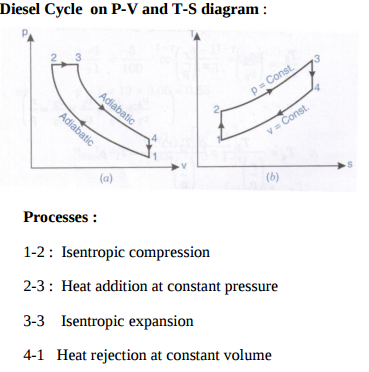 |
4 |
view |
| Q 1a)(c) |
Question:
Give the classification of air-compressors Answer:
|
4 |
view |
| Q 1a)(d) |
Question:
Explain with neat sketch working principle of Lobe compressor Answer:
|
4 |
view |
| Q 1b)(a) |
Question:
State different methods of determining frictional power of I.C. engine and explain any one method Answer:
|
6 |
view |
| Q 1b)(b) |
Question:
Explain with neat sketch working principle of any one type of catalytic converter. Answer:
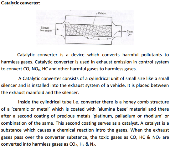 |
6 |
view |
| Q 1b)(i) |
Question:
Define : i) Brake thermal efficiency ii) BSFC related to I.C. Engine. Answer:
|
4 |
view |
| Q 2 a ) |
Question:
Following observations were recorded during a trial on single cylinder four stroke oil engine : Cylinder bore = 15 cm Length of stroke = 25 cm Mean effective pressure = 7.35 bar Engine speed = 400 rpm Brake torque = 225 N.m. Fuel consumption = 3 kg/hr Calorific value of fuel = 44200 kJ/kg. Determine : i) Mechanical efficiency ii) Brake thermal efficiency iii) Brake specific fuel consumption. Answer:
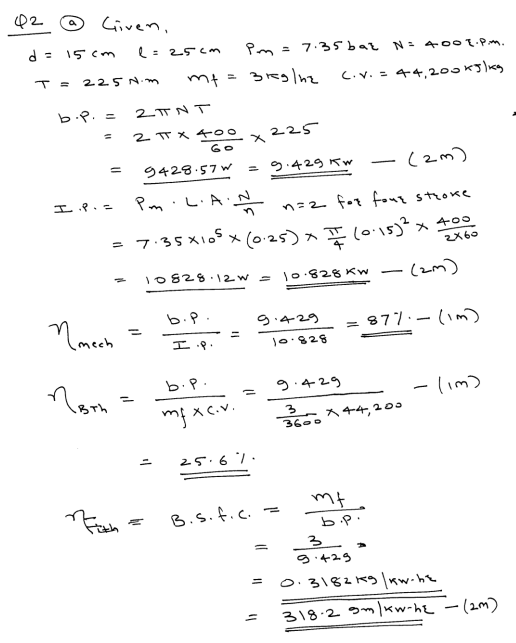 |
8 |
view |
| Q 2 b ) |
Question:
Explain construction and working of single stage reciprocating air compressor with neat sketch. Also represent it on P-V diagram. Answer:
|
8 |
view |
| Q 2 c ) |
Question:
Explain working principle of simple vapour absorption refrigeration system. Represent it on the block diagram. Answer:
|
8 |
view |
| Q 3 a ) |
Question:
Draw turning moment diagram for four stroke petrol engine and explain it in brief. Answer:
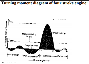 |
4 |
view |
| Q 3 b ) |
Question:
What is supercharging ? State advantages of supercharging. Answer:
|
4 |
view |
| Q 3 c ) |
Question:
State effects of pollutants in exhaust gases of petrol engine. Answer:
|
4 |
view |
| Q 3 d ) |
Question:
Explain with neat sketch working principle of Ram jet engine Answer:
|
4 |
view |
| Q 3 e ) |
Question:
Represent wet compression and dry compression on T-S and P-H diagram and name all processes involved in it Answer:
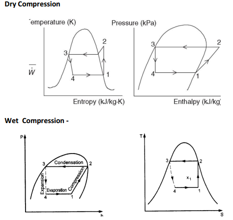 |
4 |
view |
| Q 4a)(a) |
Question:
What are the effects of detonation in I.C. engine ? Answer:
|
4 |
view |
| Q 4a)(b) |
Question:
Define : i) Mechanical efficiency ii) Volumetric efficiency related to I.C. engine. Answer:
|
4 |
view |
| Q 4a)(c) |
Question:
State advantages of closed cycle gas turbine. Answer:
|
4 |
view |
| Q 4b)(a) |
Question:
Explain with neat sketch working principle of four stroke petrol engine. Answer:
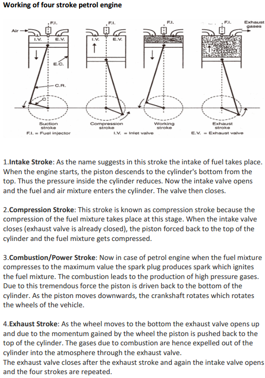 |
6 |
view |
| Q 4b)(b) |
Question:
The following data is collected during a trial of four stroke four cylinder petrol engine. B.P. with all cylinders working = 14.7 kW B.P. with cylinder no. 1 cut off = 10.14 kW B.P. with cylinder no. 2 cut off = 10.3 kW B.P. with cylinder no. 3 cut off = 10.36 kW B.P. with cylinder no. 4 cut off = 10.21 kW Find mechanical efficiency of engine. Answer:
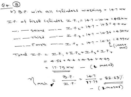 |
6 |
view |
| Q 4 d ) |
Question:
State advantages of jet propulsion over other systems. Answer:
|
4 |
view |
| Q 5a)(i) |
Question:
Compare reciprocating and rotary compressors (any four). Answer:
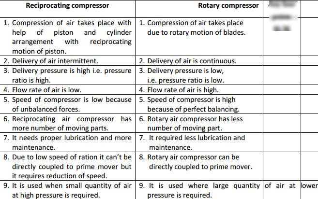 |
8 |
view |
| Q 5a)(ii) |
Question:
Write any four applications of compressed air. Answer:
|
8 |
view |
| Q 5 b ) |
Question:
List the methods to improve thermal efficiency of gas turbine and explain any one of them in detail Answer:
|
8 |
view |
| Q 5 c ) |
Question:
Explain with neat sketch working principle of Ice plant. Answer:
|
8 |
view |
| Q 6 a ) |
Question:
State any four types of sensors used in I.C. engine. Answer:
|
4 |
view |
| Q 6 b ) |
Question:
Define : i) Isothermal efficiency. ii) Volumetric efficiency with respect to air compression. Answer:
|
4 |
view |
| Q 6 c ) |
Question:
Explain with neat sketch working principle of turbo jet engine. Answer:
|
4 |
view |
| Q 6 d ) |
Question:
Define : i) DBT ii) WBT iii) DPT iv) Relative humidity. Answer:
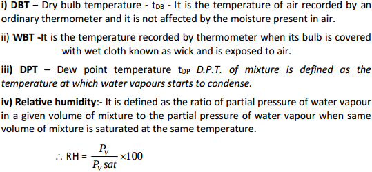 |
4 |
view |
| Q 6 e ) |
Question:
Give the classification of air conditioning systems. Answer:
|
4 |
view |